Руководство пользователя EdgeTX
.png)
Это неофициальный перевод EdgeTX User Manual, созданный для популяризации EdgeTX и радиоуправляемых моделей среди русскоязычных пользователей. В тексте "аппаратура радиоуправления", "аппаратура", "пульт управления" и просто "пульт" используются взаимозаменяемо для упрощения подачи информации. Некоторые англоязычные термины переводятся с указанием оригинала в скобках или транслитерируются вместо перевода, т.к. являются устоявшимися терминами и не имеют общеупотребительных аналогов в русском языке. Если вы хотели бы дополнить это руководство, см. Дополнить документацию. Примечание: на данный момент перевод руководства пользователя не окончен и часть статей имеют исходный язык и форматирование. Перевод раздела 4 доступен в формате pdf, см. Другие переводы этого руководства.
Цель этого документа - собрать в одном месте информацию по установке, настройке и использованию EdgeTX. Он включает в себя следующие разделы:
Руководство пользователя EdgeTX
Руководство пользователя рассказывает о всех возможных настройках аппаратуры управления в EdgeTX, а также содержит теоретическую информацию об использовании EdgeTX и настройках радиоуправляемых моделей. Оно разбито на подразделы, описывающие пользовательский интерфейс для Аппаратуры управления с цветным дисплеем и Аппаратуры управления с чёрно-белым дисплеем.
Инструкции EdgeTX (How-to)
Раздел "Инструкции" содержит детальные шаги по настройке аппаратуры для популярных и редких сценариев использования EdgeTX и настройки радиоуправляемых моделей. Желающие пополнить этот раздел своими инструкциями, см. Дополнить документацию.
Дополнительные ссылки для пользователей EdgeTX
Этот раздел содержит ссылки на сторонние ресурсы, которые могут быть полезными пользователям EdgeTX. Имейте ввиду, что эти ресурсы не контролируются авторами данного перевода и не всегда являются официальными, поэтому могут требовать перепроверки.
Отдельное спасибо всем, кто внёс свой вклад в создание этого руководства прямо или косвенно.
См. раздел Благодарности чтобы узнать о тех, кто причастен к созданию этого документа.
Список изменений с версии v2.10
Ниже представлен список изменений, затрагивающих интерфейс пользователя и/или функционал EdgeTX. Он не включает в себя описание всех исправлений и улучшений, для полного списка изменений см. Release Notes в официальном репозитории EdgeTX.
Общие изменения
-
Поддержка аппаратур управления следующего поколения (на базе микроконтроллеров H5/H7) с лучшей производительностью, большим объёмом RAM и флеш-памяти для новых функций и возможностей #5228
-
При использовании GPS приёмника на аппаратуре управления, теперь можно использовать бинарный протокол u-blox (а не только NMEA) #4689
-
При редактировании коэффициентов датчиков телеметрии теперь отображается и процентное значение #4649
-
Обновление Lua до версии 5.3 (ранее 5.2). Это снижает использование RAM памяти и обеспечивает бинарную совместимость с Companion (файлы
.luacиз симулятора теперь совместимы с пультом) #4203 -
ELRSv4: добавлен режим тренера Master/CRSF для передачи данных head-tracker через ELRS backpack в качестве входных #5724
-
ELRSv4: поддержка альтернативного метода arm, освобождающего 5 канал CH5 #5641
-
Для пультов с настраиваемыми переключателями теперь легко можно создавать виртуальные 6-позиционные группы и другие комбинации (GRx) #5016
-
Вибрация (haptic) при включении теперь может быть отключена #5017
-
Аппаратура может быть настроена на автоматическое выключение при бездействии #3414
-
Состояние логических переключателей может сохраняться после перезагрузки #4978
-
Поддержка USB-джойстика для Android gamepad-функций #4626
-
Ещё более короткая задержка включения и выключения — 0.5 секунды #5134
-
Настройка точной задержки перехода миксов вверх/вниз (в дополнение к точной настройке slow up/down, добавленной в 2.10) #5314
Аппаратура радиоуправления с цветным дисплеем
-
Значительно улучшена производительность интерфейса по сравнению с версией 2.10 #5031
-
Размеры элементов верхней строки (виджетов) теперь можно изменять #4846
-
Во всплывающем файловом браузере добавлены фильтры для ускоренной навигации по файлам #4946
-
Добавлен полноэкранный режим Lua-виджета (App mode), предоставляющий виджету фокус для сенсорного и кнопочного ввода #4655
-
Lua-скрипты и виджеты могут использовать элементы управления LVGL (кнопки, слайдеры, поля ввода и др.) #4887, #5808
-
Вместо процентных значений каналов управления можно использовать PPM_US #4987
-
Виджеты теперь могут иметь до 10 опций (ранее — 5) #5365
Аппаратура радиоуправления с чёрно-белым дисплеем
-
Добавлены сворачиваемые разделы на вкладке настроек аппаратуры для сокращения длины страницы #5529
-
Новая специальная функция «Set Screen» позволяет переключаться на заранее настроенный экран телеметрии #5589
-
В мониторе каналов теперь отображается PPM-значение в дополнение к 0.0 / 0.00 (-100/+100) #5781
-
Добавлена возможность инверсии цвета дисплея через Hardware->Invert #4933
Установка и обновление EdgeTX
Есть несколько способов обновить EdgeTX на вашей аппаратуре управления (пульте). Можно использовать онлайн сервис EdgeTX Buddy1 или вручную установить/обновить прошивку через встроенный загрузчик. И у того и у другого способа есть свои преимущества и недостатки, так что итоговый выбор зависит от ваших предпочтений.
EdgeTX Buddy
Преимущества
- И прошивку пульта управления и содержимое карты памяти можно установить на одном сайте
- Сервис пошагово проводит пользователя через процесс установки/обновления
- Обычно это довольно простой процесс
Недостатки
- Сервис работает корректно только в веб-браузерах на основе Chromium (Google Chrome, Microsoft Edge, Brave, Opera, и т.д.)
- У вас на компьютере должны быть установлены подходящие драйвера STM32. Обычно они устанавливаются автоматически, но на некоторых компьютерах могут установиться неподходящие драйвера, это затрудняет процесс установки/обновления.
Загрузчик (Bootloader)
Преимущества
- Процесс установки всегда срабатывает
- Установка происходит быстрее
- Не зависит от вашего компьютера
Недостатки
- Файл прошивки, содержимое карты памяти и файлы озвучки необходимо скачать из разных мест и вручную записать на карту памяти.
Какой бы способ вы ни выбрали, вам в помощь найдётся инструкция. Ниже находятся ссылки на инструкции по установке и обновлению EdgeTX для разных вариантов:
Переход с OpenTX на EdgeTX
Переход с OpenTX на EdgeTX с использованием EdgeTX Buddy2
Переход с OpenTX на EdgeTX с использованием загрузчика (Bootloader)
Обновление с более ранней версии EdgeTX
Обновление с более ранней версии EdgeTX с использованием EdgeTX Buddy
Обновление с более ранней версии EdgeTX использованием загрузчика (Bootloader)
Buddy (бадди) - приятель (англ.)
OpenTX - предшественник EdgeTX, программное обеспечение для пультов радиоуправления с открытым исходным кодом
Переход с OpenTX на EdgeTX с использованием EdgeTX Buddy
Если на вашей аппаратуре управления используется прошивка OpenTX и вы хотели бы заменить её на EdgeTX, то вам потребуется установить на ваш компьютер как OpenTX Companion так и EdgeTX Companion.
Вы можете скачать OpenTX Companion по ссылке: https://downloads.open-tx.org/2.3/release/companion/.
Вы можете скачать EdgeTX Companion по ссылке: https://github.com/EdgeTX/edgetx/releases (Рекомендуется промотать страницу вниз до самой последней версии помеченной "Latest"1, раскрыть список Assets и выбрать файл с именем edgetx-cpn-[операционная система вашего ПК]-[версия].zip)
Сделайте резервную копию ваших моделей
Включите аппаратуру управления, и перейдите в Radio Settings, Hardware (Настройки аппаратуры, Аппаратные настройки) прокрутите экран вниз и выберите EEPROM backup (Резервное копирование EEPROM-памяти). Если на экране аппаратных настроек вашей аппаратуры нет такого пункта, значит она не хранит настройки в EEPROM-памяти и вы можете пропустить этот пункт.

Не выключая аппаратуру, подключите её к вашему компьютеру с помощью USB кабеля. Если на экране появляется выбор режима подключения, выберите USB Storage (USB-накопитель).
Скопируйте всё содержимое карты памяти аппаратуры (обычно появляется в виде нового диска/внешнего накопителя в проводнике) в отдельную папку на вашем компьютере. Если вы захотите вернуть прошивку OpenTX на вашу аппаратуру, эти файлы могут вам понадобиться. Если на предыдущем шаге вы сделали резервную копию EEPROM-памяти, то убедитесь, что среди скопированных данных есть папка EEPROM с недавно созданным файлом резервной копии.
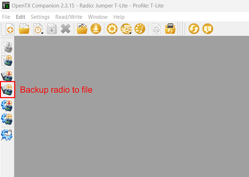
Запустите OpenTX Companion.
Нажмите на кнопку Backup radio to file (Сохранить резервную копию) на левой панели, как показано на рисунке ниже. В открывшемся диалоге выберите место сохранения резервной копии и назовите файл так, чтобы вы смогли найти его позже.
После того как файл резервной копии успешно сохранится на вашем компьютере, закройте OpenTX Companion.
Удалите содержимое папки Model (Модели) на карте памяти аппаратуры, чтобы она осталась пустой.
Отключите аппаратуру от компьютера (используйте безопасное извлечение) и выключите.
Установка загрузчика и прошивки EdgeTX
Не включая аппаратуру, подключите её к вашему компьютеру USB кабелем. Это подключит аппаратуру к компьютеру в режиме DFU2.
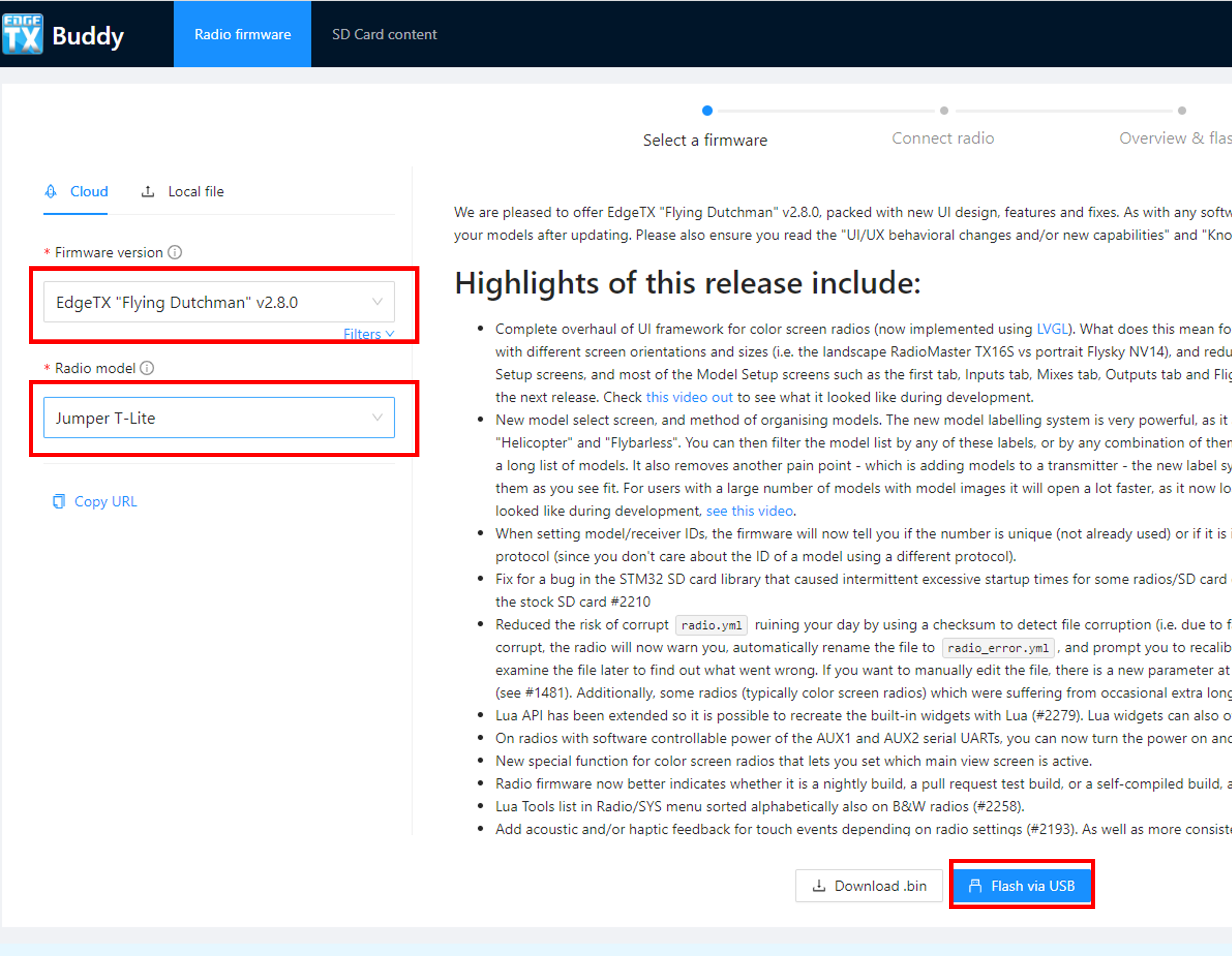
Перейдите на сайт: https://buddy.edgetx.org/
На левой панели из списка выберите Firmware version (Версия ПО) и Radio model (Модель радио, т.е. вашей аппаратуры), затем нажмите на подсвеченную кнопку Flash via USB (Прошивка через USB).
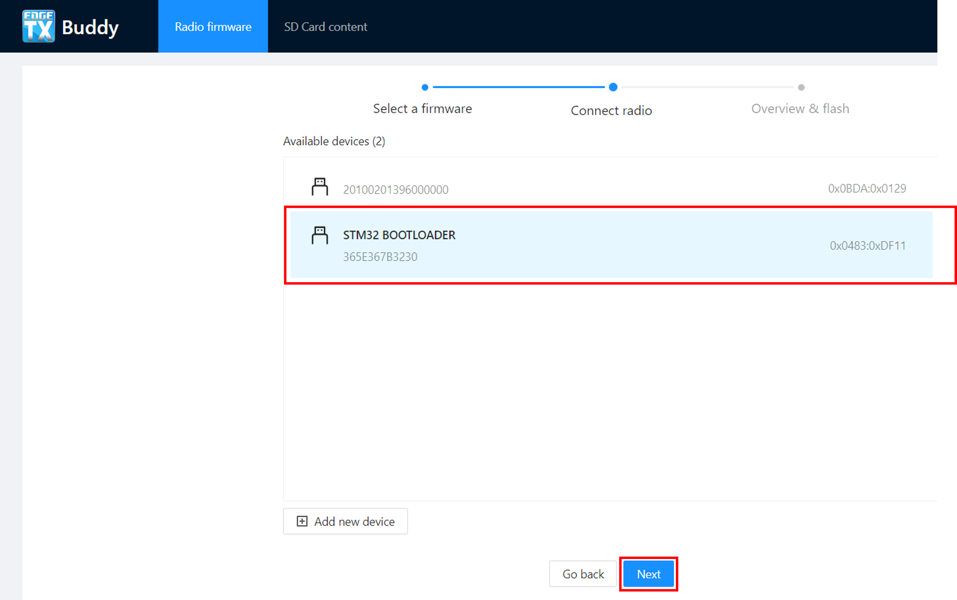
На следующем шаге, выберите устройство STM32 Bootloader и нажмите Next (Далее).
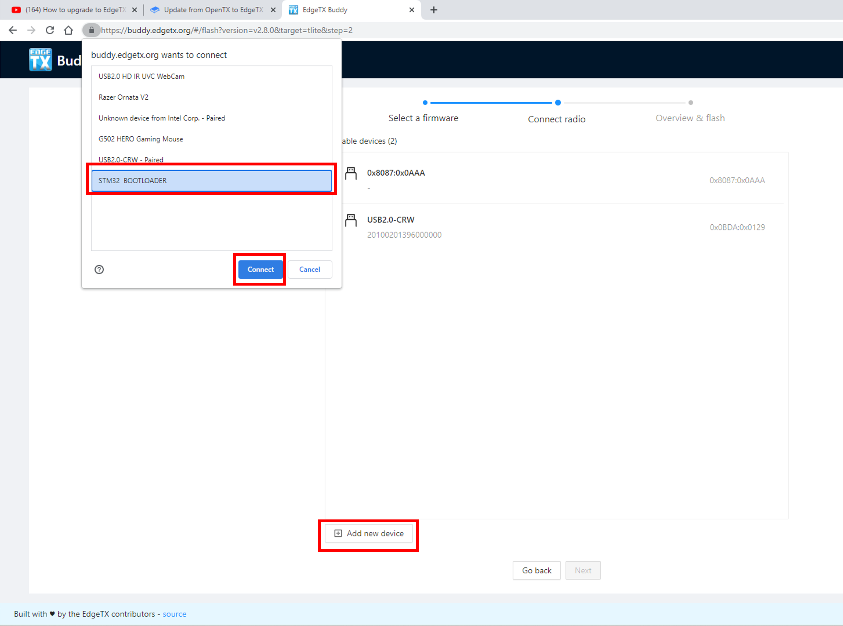
Если устройства STM32 Bootloader нет в списке, нажмите Add New Device (Добавить новое устройство). В появившемся всплывающем окне выберите STM32 Bootloader и нажмите Connect (Подключить).
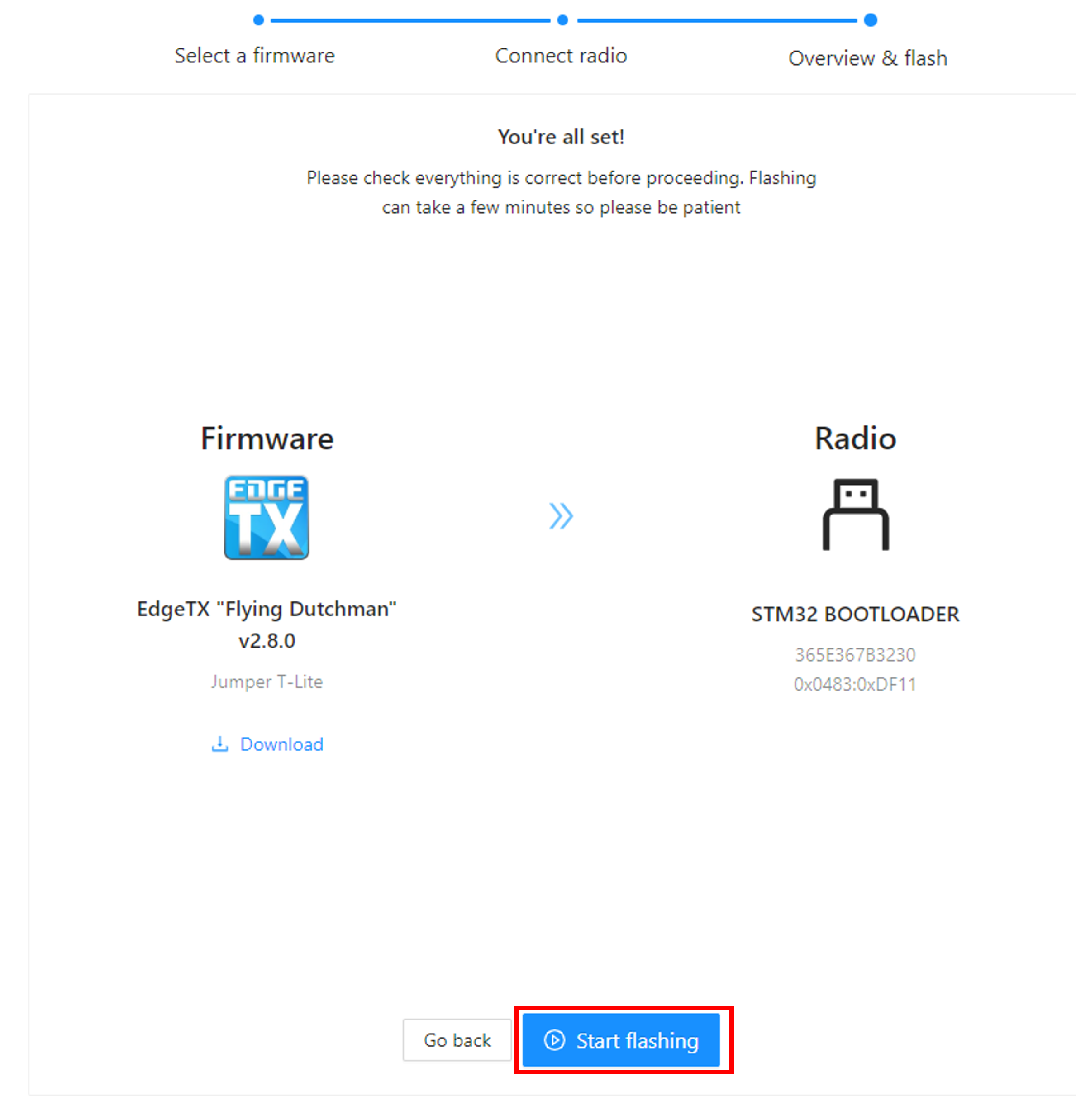
После того как вы добавили устройство STM32 Bootloader и нажали Next (Далее), вы перейдёте на экран подтверждения (Обзор и прошивка) чтобы ещё раз перепроверить настройки. Удостоверившись, что все настройки корректны (Версия EdgeTX, модель аппаратуры и подключенное по usb устройство) нажмите кнопку Start Flashing (Начать прошивку).
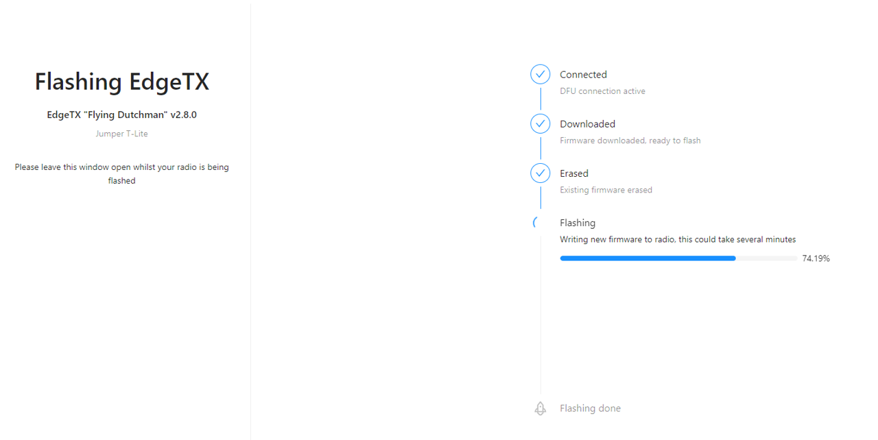
EdgeTX buddy начнёт процедуру прошивки устройства. На экране будет отображаться прогресс, процедура может занять несколько минут.
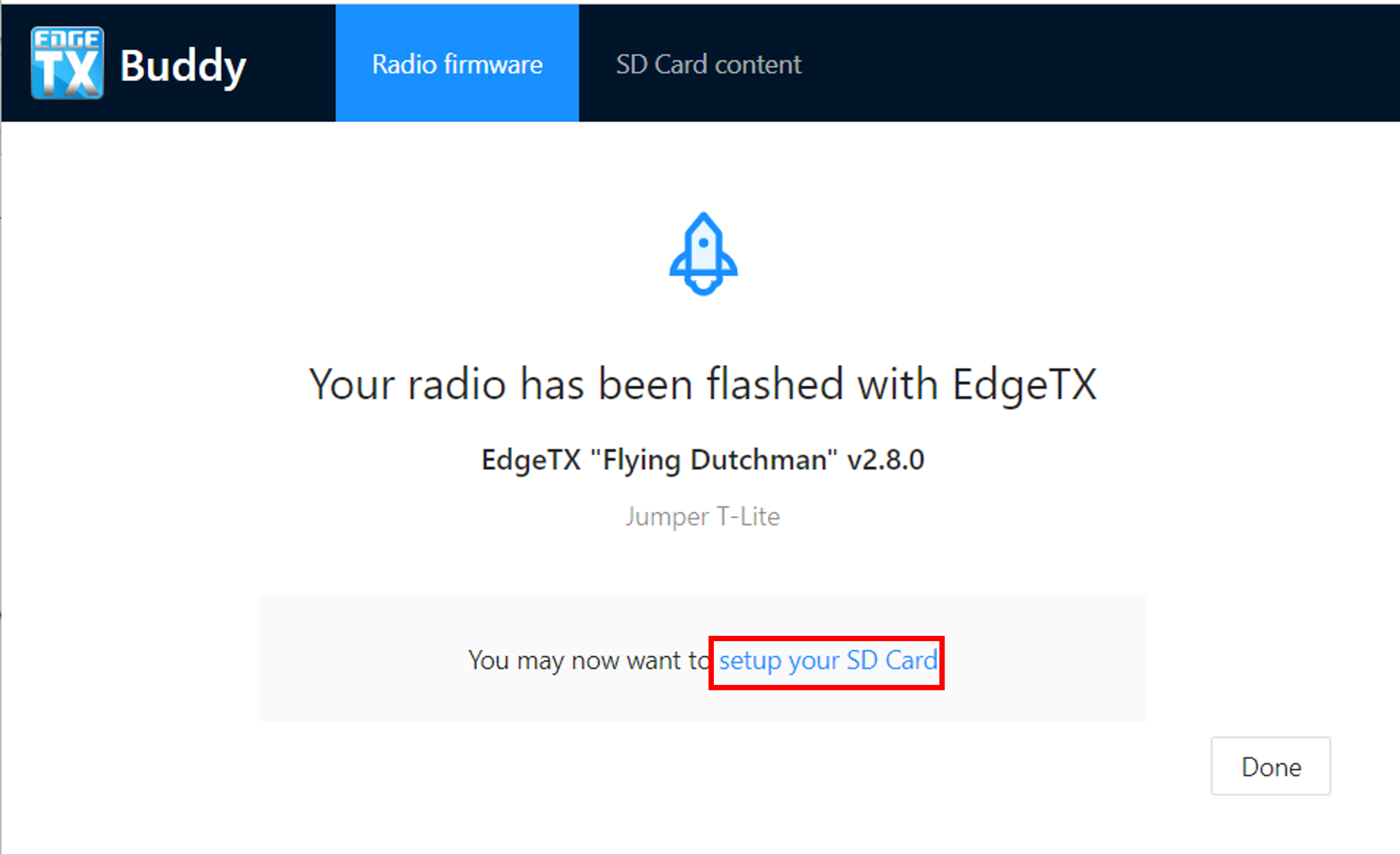
Когда прошивка устройства завершится, нажмите на ссылку setup your SD Card (настроить SD-карту памяти) на завершающем экране, чтобы перейти на экран SD Card content (Содержимое SD-карты).
На этом шаге встроенное ПО устройства (прошивка) и загрузчик EdgeTX (bootloader) уже установлены на вашу аппаратуру управления. Следующим шагом мы установим содержимое карты памяти: картинки, звуковые пакеты на желаемом языке, Lua скрипты, а также темы и виджеты для пультов управления с цветным экраном.
Подготовка карты памяти SD card
Отсоедините аппаратуру от компьютера и включите. Вы должны увидеть экран приветствия EdgeTX (splash screen), но звуковое приветствие всё ещё будет звучать как "Welcome to OpenTX" (Добро пожаловать в OpenTX). Это нормально, мы обновим звуковой пакет на EdgeTX на следующих шагах.
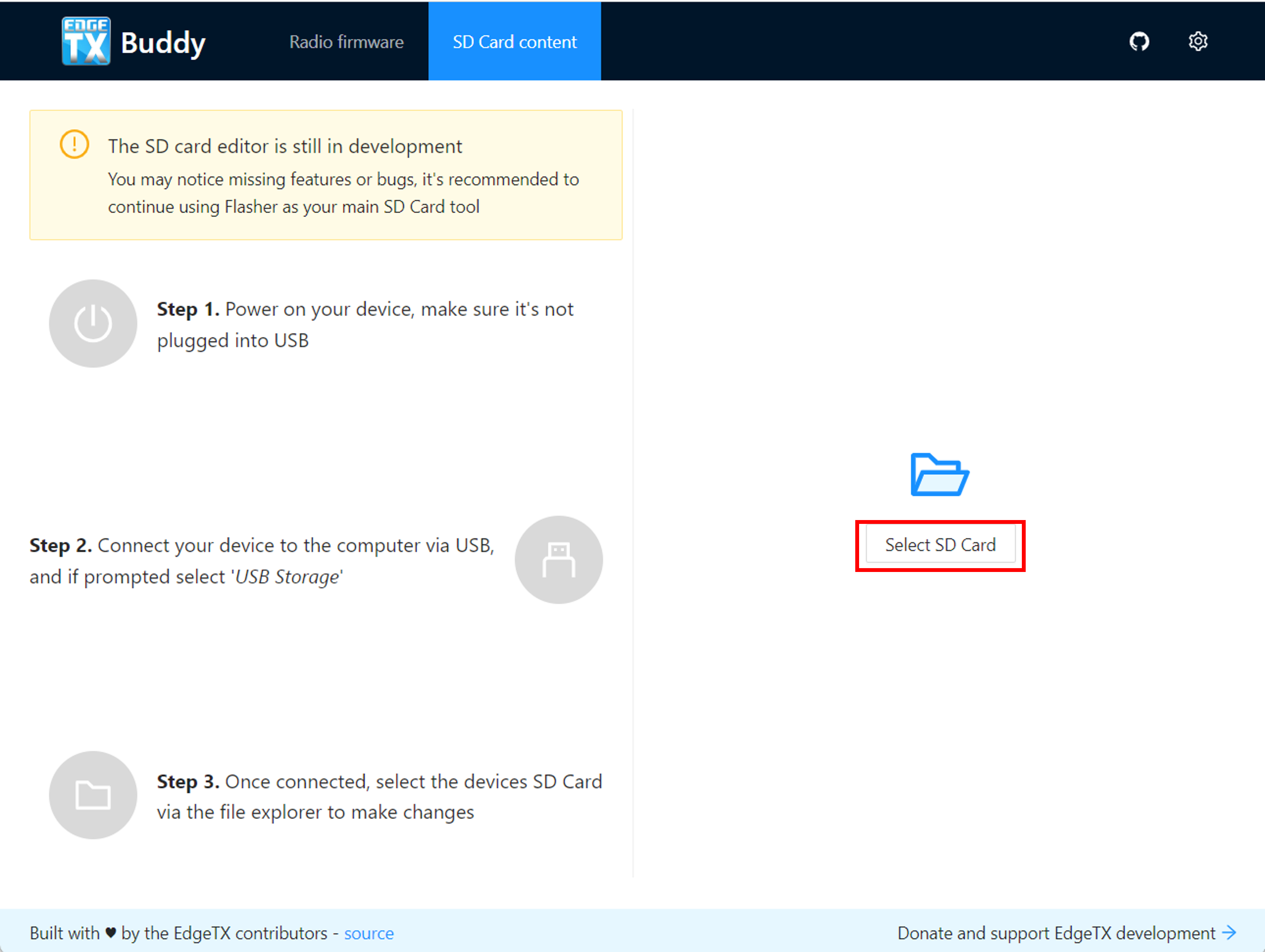
Не выключая аппаратуру, присоедините её к компьютеру USB-кабелем и выберите USB Storage (USB-накопитель) когда на экране пульта появится меню выбора вариантов подключения. В вашем браузере на странице c EdgeTX buddy нажмите на кнопку Select SD Card ("Выбор SD Card") и в проводнике выберите карту памяти вашей аппаратуры управления.
Карта памяти определится вашим компьютером как USB-накопитель, выберите нужное устройство (примечание - там всё ещё будут находиться файлы от OpenTX, так можно определить что устройство выбрано правильно) и нажмите Открыть/ОК в проводнике.
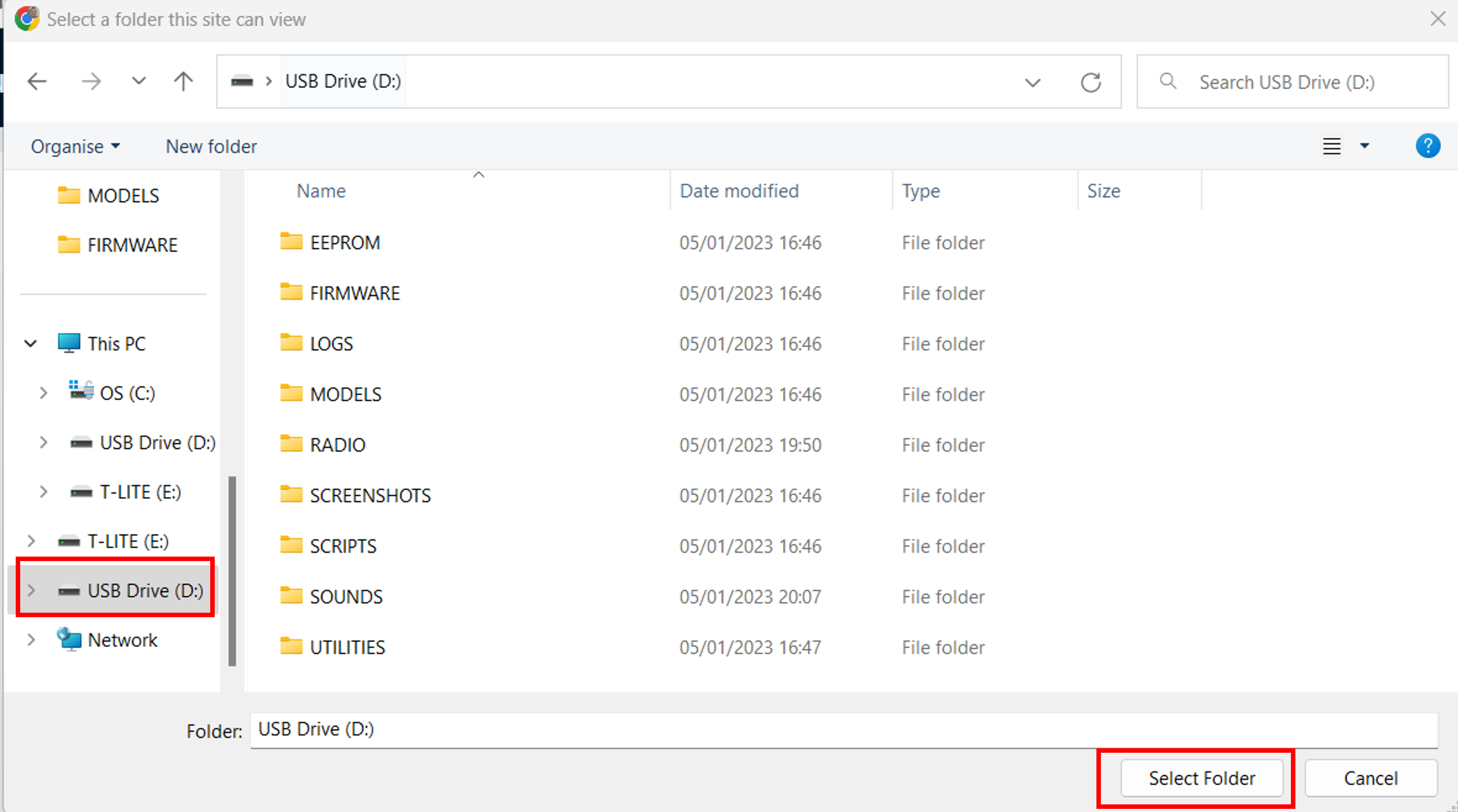
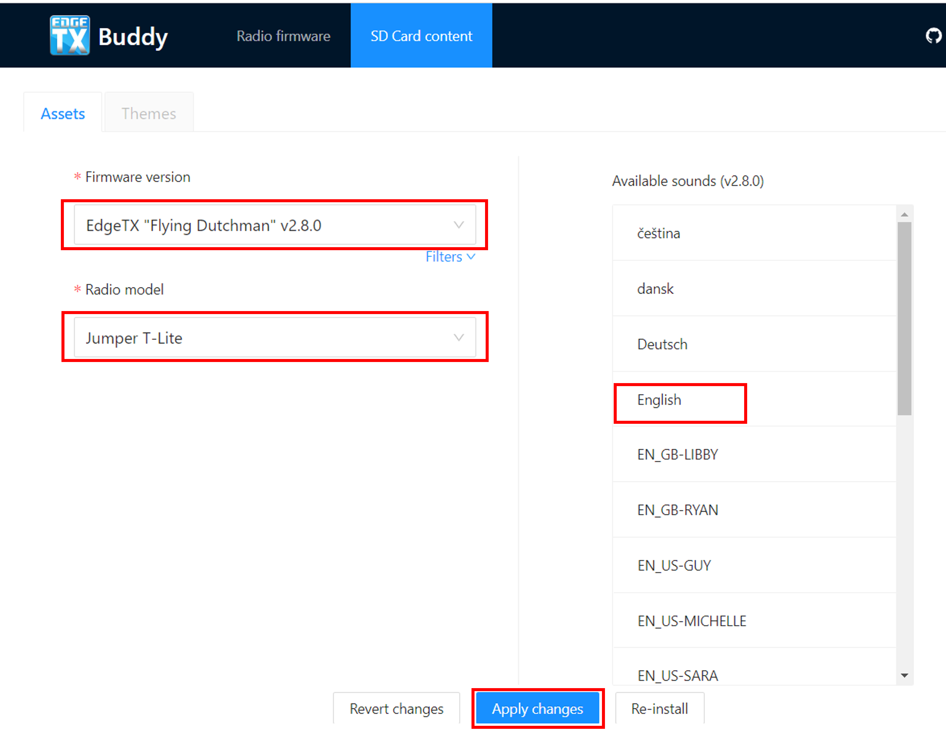
На экране "Содержимое SD-карты" ещё раз удостоверьтесь, что версия содержимого карты памяти (может незначительно отличаться от версии прошивки в последней цифре) и модель вашей аппаратуры указаны правильно, затем выберите желаемый язык озвучки и нажмите Apply Changes (Применить изменения). Появившееся всплывающее окно отобразит прогресс записи файлов на карту памяти вашего устройства, по завершении записи всплывающее окно закроется.
На этом шаге на вашем пульте управления установлена прошивка EdgeTX, загрузчик и необходимое содержимое карты памяти. Последний шаг - это конвертация ваших OpenTX моделей и запись их в память аппаратуры. Вы можете закрыть EdgeTX Buddy.
Восстановление моделей из резервной копии OpenTX
Откройте EdgeTX Companion. Если вы этого ещё не сделали, рекомендуется создать профиль для вашей аппаратуры управления и выбрать его в качестве активного.
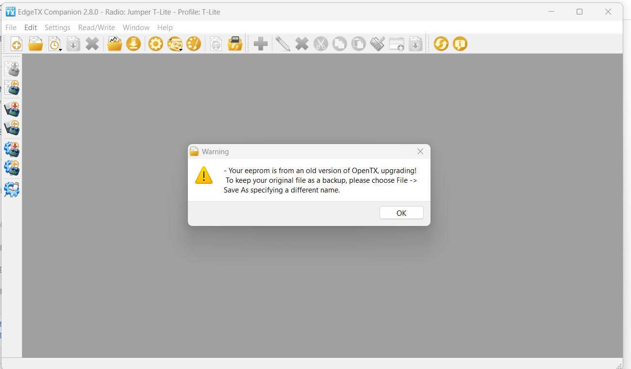
В левом верхнем углу приложения EdgeTX Companion выберите File (Файл), затем Open (Открыть), затем выберите файл резервной копии OpenTX, который вы сохранили на первом шаге. Вы увидите предупреждение (warning) о том, что резервная копия создана в старой версии OpenTX. Нажмите OK.
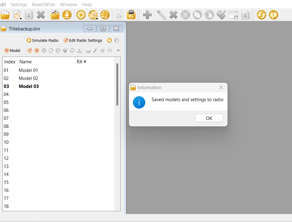
Список всех ваших моделей из резервной копии OpenTX должен появиться на экране. Нажмите на кнопку Write models and Settings to Radio (Записать модели и настройки в передатчик). Программа предупредит вас, что все модели будут перезаписаны. Нажмите Yes (ОК).
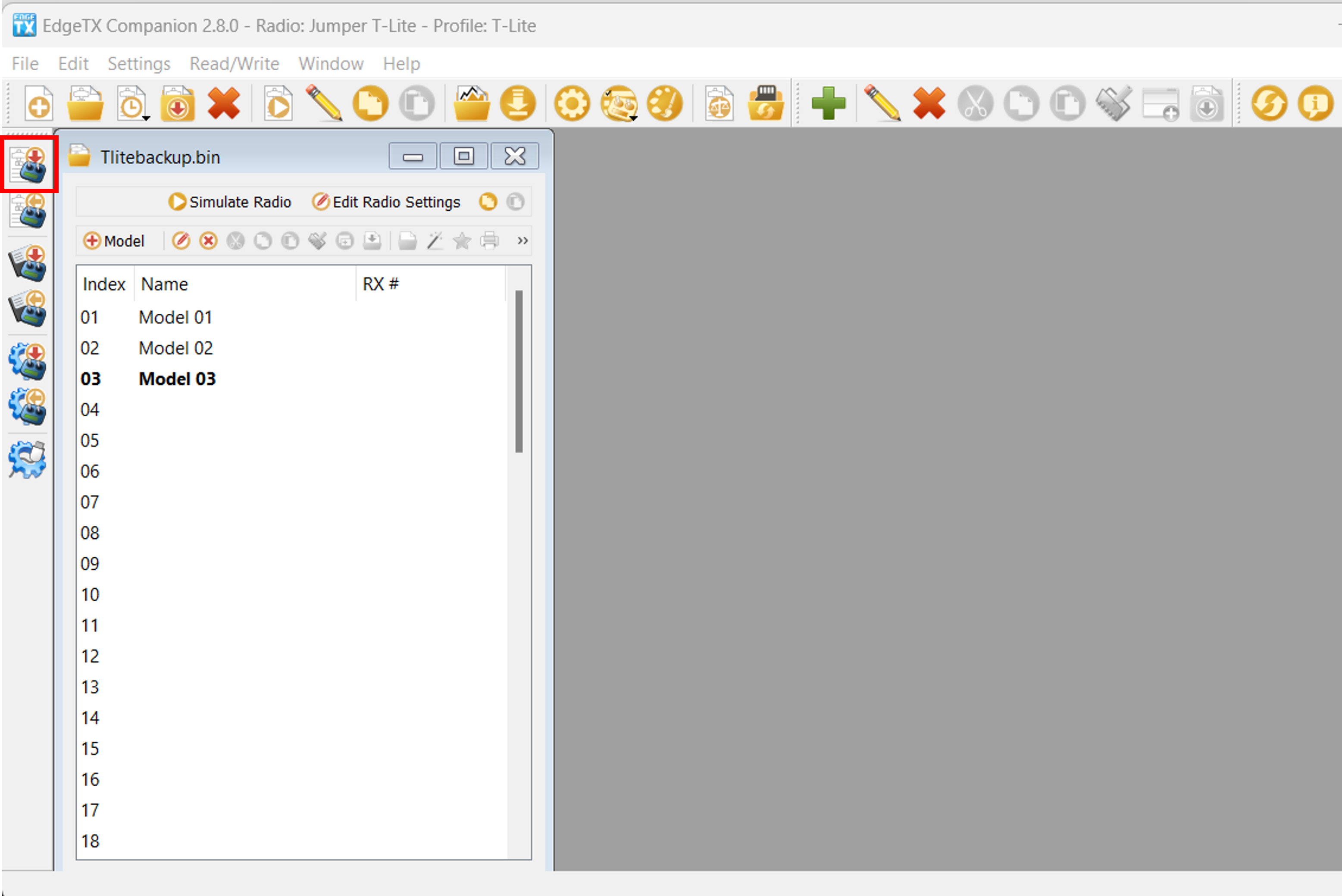
Модели и настройки будут записаны в память аппаратуры управления. По завершении записи появится информационное сообщение, нажмите OK. Отсоедините ваш пульт от компьютера и закройте EdgeTX Companion.
Поздравляем, вы успешно перешли на EdgeTX!
Все ваши модели были переведены в формат .yml, а звуки устройства заменены на звуковой пакет EdgeTX. Теперь вы готовы к использованию EdgeTX.
На момент перевода это версия 2.10.6 "Centurion"
DFU (Device Firmware Update) - "Обновление прошивки устройства", специальный низкоуровневый режим работы аппаратуры, в котором все высокоуровневые функции отключены и контроль полностью передаётся внешнему устройству (компьютеру). Позволяет полностью перезаписать встроенное программное обеспечение.
Переход с OpenTX на EdgeTX с использованием загрузчика (Bootloader)
Если на вашей аппаратуре управления используется прошивка OpenTX и вы хотели бы заменить её на EdgeTX, то вам потребуется установить на ваш компьютер как OpenTX Companion так и EdgeTX Companion.
Вы можете скачать OpenTX Companion по ссылке: https://downloads.open-tx.org/2.3/release/companion/.
Вы можете скачать EdgeTX Companion по ссылке: https://github.com/EdgeTX/edgetx/releases (Рекомендуется промотать страницу вниз до самой последней версии помеченной "Latest", раскрыть список Assets и выбрать файл с именем edgetx-cpn-[операционная система вашего ПК]-[версия].zip)
Сделайте резервную копию ваших моделей
Включите аппаратуру управления, и перейдите в Radio Settings, Hardware (Настройки аппаратуры, Аппаратные настройки) прокрутите экран вниз и выберите EEPROM backup (Резервное копирование EEPROM-памяти). Если на экране аппаратных настроек вашей аппаратуры нет такого пункта, значит она не хранит настройки в EEPROM-памяти и вы можете пропустить этот пункт.
Не выключая аппаратуру, подключите её к вашему компьютеру с помощью USB кабеля. Если на экране появляется выбор режима подключения, выберите USB Storage (USB-накопитель).
Скопируйте всё содержимое карты памяти аппаратуры (обычно появляется в виде нового диска/внешнего накопителя в проводнике) в отдельную папку на вашем компьютере. Если вы захотите вернуть прошивку OpenTX на вашу аппаратуру, эти файлы могут вам понадобиться. Если на предыдущем шаге вы сделали резервную копию EEPROM-памяти, то убедитесь, что среди скопированных данных есть папка EEPROM с недавно созданным файлом резервной копии.
Запустите OpenTX Companion.
Нажмите на кнопку Backup radio to file (Сохранить резервную копию) на левой панели, как показано на рисунке ниже. В открывшемся диалоге выберите место сохранения резервной копии и назовите файл так, чтобы вы смогли найти его позже.
После того как файл резервной копии успешно сохранится на вашем компьютере, закройте OpenTX Companion. Отключите аппаратуру от компьютера (используйте безопасное извлечение) и выключите.
Подготовка карты памяти (SD Card)
Скачайте архив с содержимым карты памяти для вашей модели аппаратуры и распакуйте его на компьютере. Архивы с содержимым карты памяти можно найти по ссылке: https://github.com/EdgeTX/edgetx-sdcard/releases
Какой архив необходимо скачать для вашей модели пульта управления, в зависимости от типа экрана на нём:
- c480x272.zip (480x272 горизонтальный цветной экран)
- FrSky Horus x10s
- FrSky Horus x12s
- Jumper T16
- Jumper T18
- RadioMaster TX16s / TX16s mkII
- c480x320.zip (480x320 горизонтальный цветной экран)
- Flysky PL18
- Flysky Paladin EV (PL18EV)
- Jumper T15
- c320x480.zip (320x480 вертикальный цветной экран)
- Flysky Nirvana NV14
- Flysky Elysium EL18
- bw128x64.zip (128x64 чёрно-белый экран)
- BetaFPV LiteRadio3 Pro
- FrSky Taranis Q X7
- FrSky Taranis X-Lite
- FrSky Taranis X9 Lite
- iFlight Commando 8
- Jumper T20
- Jumper T-Lite
- Jumper T-Pro / T-Pro v2
- RadioMaster Boxer
- RadioMaster Pocket
- RadioMaster TX12 / TX12 mkII
- RadioMaster MT12
- RadioMaster Zorro
- bw212x64.zip (212x64 "широкий" чёрно-белый экран)
- FrSky Taranis X9D
- FrSky Taranis X9D+
- FrSky Taranis X9D+ 2019
Удалите файлы с вашей карты памяти и скопируйте на очищенную карту содержимое распакованного .zip архива. (Если вы форматировали карту, убедитесь что она отформатирована в fat32)
Если у вас есть пользовательская озвучка, картинки моделей, виджеты или Lua скрипты, скопируйте их в соответствующие папки.
Скачайте желаемый звуковой пакет (если вы не копировали пользовательский звуковой пакет на предыдущем шаге) (https://github.com/EdgeTX/edgetx-sdcard-sounds/releases), распакуйте архив и скопируйте папку "Sounds" (Звуки) на вашу карту памяти.
Прошивка загрузчика и основного ПО EdgeTX
Скачайте текущую версию встроенного ПО (прошивки) EdgeTX. Вы можете скачать .zip файл с последней версией прошивки (edgetx-firmware-vX.X.X.zip) напрямую с Github - https://github.com/EdgeTX/edgetx/releases/latest
Распакуйте архив, найдите файл .bin соответствующий вашей модели пульта управления и скопируйте его в папку "Firmware" карты памяти.
Включите вашу аппаратуру, нажмите кнопку SYS и перейдите на второй экран SD card (карта памяти). Откройте папку "Firmware" и выберите файл прошивки EdgeTX, который вы скопировали на карту памяти на предыдущем шаге. Когда файл прошивки выбран (напр. долгим нажатием на ролик прокрутки), в появившемся меню выберите вариант "Flash bootloader" ("ПРОШИТЬ ПО"1). Встроенная программа-загрузчик будет заменена на загрузчик EdgeTX.
Вернитесь на главный экран (кнопка RTN) и выключите аппаратуру управления.
Для того чтобы включить вашу аппаратуру в режиме загрузчика2 сведите в центр горизонтальные триммеры Т4 и Т1, и одновременно зажмите кнопку включения питания до включения аппаратуры.
На аппаратуре Jumper T-Pro необходимо зажать кнопку Boot0 и подключить её к компьютеру USB-кабелем, чтобы включить режим DFU.
Вы должны увидеть экран загрузчика EdgeTX. Выберите пункт "Write Firmware" (Записать прошивку). Выберите .bin файл прошивки, который вы сохранили на карте памяти и использовали ранее3 при установке загрузчика. Долгое нажатие запустит процесс установки.
После того как прошивка завершится, выберите пункт меню "Exit". Аппаратура перезагрузится и вы должны услышать приветствие "Welcome to EdgeTX" (Добро пожаловать в EdgeTX).
Когда EdgeTX запускается в первый раз, вы получите предупреждение STORAGE WARNING - Missing or Bad Radio Data (Отсутствуют радиоданные). Нажмите на ролик прокрутки (или белый кружок со стрелкой в правом нижнем углу, если у вас аппаратура с цветным сенсорным экраном) чтобы пропустить его. После этого вы увидите предупреждение STORAGE WARNING - Storage Preparation (Формат памяти). Снова нажмите на валик прокрутки или кружок со стрелкой. Когда завершится подготовка карты памяти, появится экран калибровки. Откалибруйте вашу аппаратуру.
На этом шаге на вашем пульте управления установлена прошивка EdgeTX, загрузчик и необходимое содержимое карты памяти. Последний шаг - это конвертация ваших OpenTX моделей и запись их в память аппаратуры.
Восстановление моделей из резервной копии OpenTX
Включите вашу аппаратуру и присоедините её к компьютеру кабелем USB. В появившемся меню выберите режим подключения USB Storage ("USB Карта SD (SD)").
Откройте EdgeTX Companion. Если вы этого ещё не сделали, рекомендуется создать профиль для вашей аппаратуры управления и выбрать его в качестве активного.
В левом верхнем углу приложения EdgeTX Companion выберите File (Файл), затем Open (Открыть), затем выберите файл резервной копии OpenTX, который вы сохранили на первом шаге. Вы увидите предупреждение (warning) о том, что резервная копия создана в старой версии OpenTX. Нажмите OK.
Список всех ваших моделей из резервной копии OpenTX должен появиться на экране. Нажмите на кнопку Write models and Settings to Radio (Записать модели и настройки в передатчик). Программа предупредит вас, что все модели будут перезаписаны. Нажмите Yes (ОК).
Модели и настройки будут записаны в память аппаратуры управления. По завершении записи появится информационное сообщение, нажмите OK. Отсоедините ваш пульт от компьютера и закройте EdgeTX Companion.
Поздравляем, вы успешно перешли на EdgeTX!
Все ваши модели были переведены в формат .yml, а звуки устройства заменены на звуковой пакет EdgeTX. Теперь вы готовы к использованию EdgeTX.
Bootloader (загрузчик) - это небольшая программа, хранящаяся в постоянной памяти устройства, которая запускается при включении устройства и отвечает за загрузку основной прошивки. Она инициализирует аппаратные компоненты (экран, нажатия кнопок), проверяет целостность основной прошивки и передаёт ей управление, а также может использоваться для обновления или восстановления системы без специального оборудования, например, через USB порт или карту памяти.
Bootloader mode (режим загрузчика) — это специальный режим работы устройства, в котором запускается только программа-загрузчик, не передавая управление основной прошивке. В этом режиме можно обновлять, переустанавливать или восстанавливать прошивку, обычно через USB порт или карту памяти, прежде чем устройство загрузится в нормальном режиме.
Мы используем один и тот же .bin файл, т.к. он содержит в себе и загрузчик (для STM32 чипов, используемых в большинстве аппаратур, это обычно первые 32 КБ памяти) и основную прошивку (оставшаяся часть). Таким образом, обновление загрузчика и обновление основной прошивки — это два разных процесса, но для них используется один и тот же .bin файл (из которого загружается нужная часть и записывается в соответствующий раздел в постоянной памяти устройства).
Обновление с более ранней версии EdgeTX с использованием EdgeTX Buddy
Создание резервной копии карты памяти SD Card
Мы рекомендуем ВСЕГДА создавать резервную копию данных на вашей карте памяти перед внесением значительных изменение в конфигурацию вашей аппаратуры или обновлением прошивки.
Включите вашу аппаратуру и подсоедините к компьютеру USB кабелем. В появившемся меню выберите USB Storage (USB Карта SD (SD)).
Скопируйте всё содержимое карты памяти аппаратуры (обычно появляется в виде нового диска/внешнего накопителя в проводнике) в отдельную папку на вашем компьютере. Если вы захотите вернуть старую версию прошивки на вашу аппаратуру, эти файлы могут вам понадобиться. После этого отключите аппаратуру от компьютера (через безопасное извлечение) и выключите.
Обновление загрузчика (bootloader) и основной прошивки
Не включая аппаратуру, подключите её к вашему компьютеру USB-кабелем. Это подключит её к компьютеру в режиме DFU1.
На аппаратуре Jumper T-Pro необходимо зажать кнопку Boot0 и подключить её к компьютеру USB-кабелем, чтобы включить режим DFU.
Перейдите на сайт: https://buddy.edgetx.org/
На левой панели из списка выберите Firmware version (Версия ПО) и Radio model (Модель радио, т.е. вашей аппаратуры), затем нажмите на подсвеченную кнопку Flash via USB (Прошивка через USB).
На следующем шаге, выберите устройство STM32 Bootloader и нажмите Next (Далее).
Если устройства STM32 Bootloader нет в списке, нажмите Add New Device (Добавить новое устройство). В появившемся всплывающем окне выберите STM32 Bootloader и нажмите Connect (Подключить).
Если вам не удаётся добиться определения устройства STM32 BOOTLOADER даже с помощью ImpulseRC Driver Fixer, тогда вам придётся воспользоваться способом обновления EdgeTX с помощью загрузчика2. Пропустите оставшиеся шаги в этом разделе и перейдите к разделу Обновление содержимого карты памяти. После этого раздела мы приводим шаги обновления прошивки через встроенный загрузчик EdgeTX.
После того как вы добавили устройство STM32 Bootloader и нажали Next (Далее), вы перейдёте на экран подтверждения (Обзор и прошивка) чтобы ещё раз перепроверить настройки. Удостоверившись, что все настройки корректны (Версия EdgeTX, модель аппаратуры и подключенное по usb устройство) нажмите кнопку Start Flashing (Начать прошивку).
EdgeTX buddy начнёт процедуру прошивки устройства. На экране будет отображаться прогресс, процедура может занять несколько минут.
Следующим шагом после завершения прошивки идёт обновление содержимого карты памяти вашей аппаратуры управления. Это не всегда необходимо, однако рекомендуется выполнять этот шаг при значительном изменении версии прошивки. Нажмите на ссылку setup your SD Card (настроить SD-карту памяти) на завершающем экране, чтобы перейти на экран SD Card content (Содержимое SD-карты).
Обновление содержимого карты памяти
Отсоедините аппаратуру от компьютера и включите.
Не выключая аппаратуру, присоедините её к компьютеру USB-кабелем и выберите USB Storage ("USB Карта SD (SD)"), когда на экране пульта появится меню выбора вариантов подключения. В вашем браузере на странице c EdgeTX buddy нажмите на кнопку Select SD Card ("Выбор SD Card") и в проводнике выберите карту памяти вашей аппаратуры управления.
Карта памяти определится вашим компьютером как USB-накопитель, выберите его и нажмите Открыть/ОК в проводнике.
На экране "Содержимое SD-карты" ещё раз удостоверьтесь, что версия содержимого карты памяти (может незначительно отличаться от версии прошивки в последней цифре) и модель вашей аппаратуры указаны правильно, затем выберите желаемый язык озвучки и нажмите Apply Changes (Применить изменения). Появившееся всплывающее окно отобразит прогресс записи файлов на карту памяти вашего устройства, по завершении записи всплывающее окно закроется.
Поздравляем, вы успешно обновили EdgeTX!
Если ранее вам не удалось установить новую прошивку с помощью EdgeTX Buddy, следуйте шагам ниже для обновления прошивки с помощью загрузчика (bootloader). Оставьте вашу аппаратуру подключенной к компьютеру в режиме USB Storage ("USB Карта SD (SD)").
Обновление прошивки с помощью загрузчика
В вашем браузере с открытым EdgeTX buddy перейдите обратно на вкладку Radio Firmware (Прошивка радио).
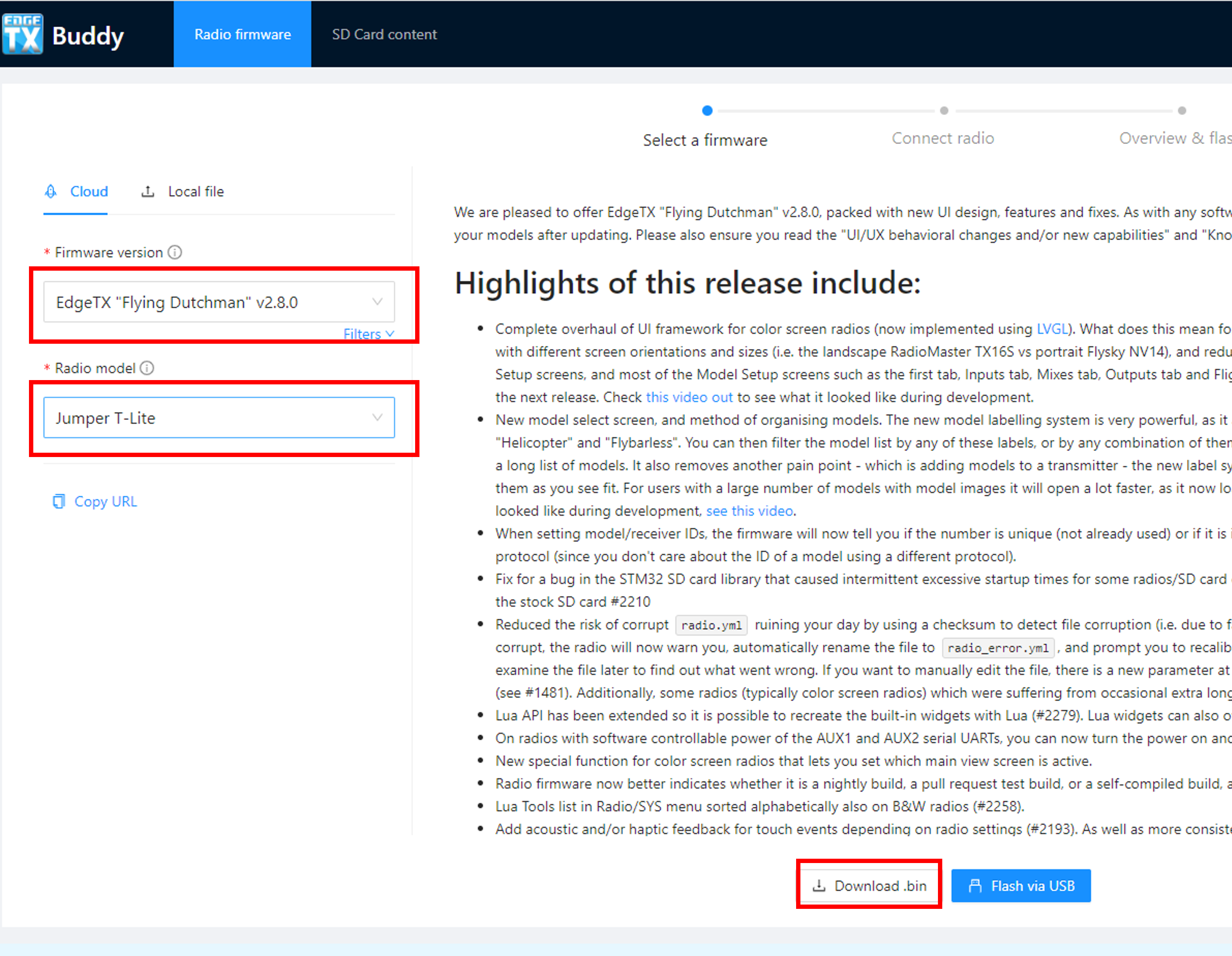
На левой панели выберите необходимую версию EdgeTX в списке Firmware version (Версия ПО) и модель вашей аппаратуры в списке Radio model (Модель радио), затем нажмите на кнопку Download .bin (Загрузка .bin).
Когда файл прошивки загрузится, появится диалоговое окно сохранения файла. В этом окне перейдите на карту памяти аппаратуры и выберите папку Firmware, нажмите Сохранить.
Отключите аппаратуру управления от компьютера (используйте безопасное извлечение) и выключите.
Для того чтобы включить вашу аппаратуру в режиме загрузчика3 сведите в центр горизонтальные триммеры Т4 и Т1, и одновременно зажмите кнопку включения питания до включения аппаратуры.
Вы должны увидеть экран загрузчика EdgeTX. Выберите пункт "Write Firmware" (Записать прошивку). Выберите .bin файл прошивки, который вы сохранили на карте памяти. Долгое нажатие запустит процесс установки.
После того как прошивка завершится, выберите пункт меню "Exit". Аппаратура перезапустится с обновлённой версией EdgeTX.
Поздравляем, вы успешно обновили EdgeTX!
DFU (Device Firmware Update) - "Обновление прошивки устройства", специальный низкоуровневый режим работы аппаратуры, в котором все высокоуровневые функции отключены и контроль полностью передаётся внешнему устройству (компьютеру). Позволяет полностью перезаписать встроенное программное обеспечение.
Загрузчик (bootloader) - это небольшая программа, хранящаяся в постоянной памяти устройства, которая запускается при включении устройства и отвечает за загрузку основной прошивки. Она инициализирует аппаратные компоненты (экран, нажатия кнопок), проверяет целостность основной прошивки и передаёт ей управление, а также может использоваться для обновления или восстановления системы без специального оборудования, например, через USB порт или карту памяти.
Bootloader mode (режим загрузчика) — это специальный режим работы устройства, в котором запускается только программа-загрузчик, не передавая управление основной прошивке. В этом режиме можно обновлять, переустанавливать или восстанавливать прошивку, обычно через USB порт или карту памяти, прежде чем устройство загрузится в нормальном режиме.
Обновление с более ранней версии EdgeTX с использованием загрузчика (Bootloader)
Создание резервной копии карты памяти SD Card
Мы рекомендуем ВСЕГДА создавать резервную копию данных на вашей карте памяти перед внесением значительных изменение в конфигурацию вашей аппаратуры или обновлением прошивки.
Включите вашу аппаратуру и подсоедините к компьютеру USB кабелем. В появившемся меню выберите USB Storage ("USB Карта SD (SD)").
Скопируйте всё содержимое карты памяти аппаратуры (обычно появляется в виде нового диска/внешнего накопителя в проводнике) в отдельную папку на вашем компьютере. Если вы захотите вернуть старую версию прошивки на вашу аппаратуру, эти файлы могут вам понадобиться.
Подготовка карты памяти (SD Card)
Скачайте архив с содержимым карты памяти для вашей модели аппаратуры и распакуйте его на компьютере. Архивы с содержимым карты памяти можно найти по ссылке: https://github.com/EdgeTX/edgetx-sdcard/releases
Какой архив необходимо скачать для вашей модели пульта управления, в зависимости от типа экрана на нём:
- c480x272.zip (480x272 горизонтальный цветной экран)
- FrSky Horus x10s
- FrSky Horus x12s
- Jumper T16
- Jumper T18
- RadioMaster TX16s / TX16s mkII
- c480x320.zip (480x320 горизонтальный цветной экран)
- Flysky PL18
- Flysky Paladin EV (PL18EV)
- Jumper T15
- c320x480.zip (320x480 вертикальный цветной экран)
- Flysky Nirvana NV14
- Flysky Elysium EL18
- bw128x64.zip (128x64 чёрно-белый экран)
- BetaFPV LiteRadio3 Pro
- FrSky Taranis Q X7
- FrSky Taranis X-Lite
- FrSky Taranis X9 Lite
- iFlight Commando 8
- Jumper T20
- Jumper T-Lite
- Jumper T-Pro / T-Pro v2
- RadioMaster Boxer
- RadioMaster Pocket
- RadioMaster TX12 / TX12 mkII
- RadioMaster MT12
- RadioMaster Zorro
- bw212x64.zip (212x64 "широкий" чёрно-белый экран)
- FrSky Taranis X9D
- FrSky Taranis X9D+
- FrSky Taranis X9D+ 2019
Скопируйте распакованное содержимое архива на карту памяти вашей аппаратуры. Подтвердите перезапись существующих файлов, если появится такой запрос. Это действие перезапишет те файлы на карте памяти, которые являются частью установки EdgeTX по умолчанию. Учтите это, если вы заменяли системные файлы своими, например файл звука приветствия hello.wav. Дополнительные файлы, которые вы ранее добавили на карту памяти (LUA скрипты, звуковые файлы, картинки, пользовательские темы, файлы моделей, файлы настроек) не будут изменены или удалены.
Скачайте желаемый звуковой пакет (если вы не копировали пользовательский звуковой пакет на предыдущем шаге) (https://github.com/EdgeTX/edgetx-sdcard-sounds/releases), распакуйте архив и скопируйте папку "Sounds" (Звуки) на вашу карту памяти. При запросе подтвердите перезапись уже существующих файлов.
Прошивка загрузчика и основного ПО EdgeTX
Скачайте текущую версию встроенного ПО (прошивки) EdgeTX. Вы можете скачать .zip файл с последней версией прошивки (edgetx-firmware-vX.X.X.zip) напрямую с Github - https://github.com/EdgeTX/edgetx/releases/latest
Распакуйте архив, найдите файл .bin соответствующий вашей модели пульта управления и скопируйте его в папку "Firmware" карты памяти.
Включите вашу аппаратуру, нажмите кнопку SYS и перейдите на второй экран SD card (карта памяти). Откройте папку "Firmware" и выберите файл прошивки EdgeTX, который вы скопировали на карту памяти на предыдущем шаге. Когда файл прошивки выбран (напр. долгим нажатием на валик прокрутки), в появившемся меню выберите вариант "Flash bootloader" (ПРОШИТЬ ПО1). Встроенная программа-загрузчик будет обновлена.
Примечание: Если при обновлении загрузчика EdgeTX вы не видите в меню варианта "Flash bootloader" ("ПРОШИТЬ ПО"), значит выбранный файл прошивки предназначается для другой модели аппаратуры.
Вернитесь на главный экран (кнопка RTN) и выключите аппаратуру управления.
Для того чтобы включить вашу аппаратуру в режиме загрузчика2 сведите в центр горизонтальные триммеры Т4 и Т1, и одновременно зажмите кнопку включения питания до включения аппаратуры.
На аппаратуре Jumper T-Pro необходимо зажать кнопку Boot0 и подключить её к компьютеру USB-кабелем, чтобы включить режим DFU.
Вы должны увидеть экран загрузчика EdgeTX. Выберите пункт "Write Firmware" (Записать прошивку). Выберите .bin файл прошивки, который вы сохранили на карте памяти и использовали ранее3 при установке загрузчика. Долгое нажатие запустит процесс установки.
Примечание: Если вы устанавливаете новую прошивку через загрузчик, и загрузчик определяет, что прошивка относится к модели устройства, отличающейся от той, что прошита на данный момент, вы получите сообщение об ошибке "Not a valid firmware file" (некорректный файл прошивки).
После того как прошивка завершится, выберите пункт меню "Exit". Аппаратура перезагрузится и вы должны услышать приветствие "Welcome to EdgeTX" (Добро пожаловать в EdgeTX).
Поздравляем, вы успешно обновили EdgeTX!
Bootloader (загрузчик) - это небольшая программа, хранящаяся в постоянной памяти устройства, которая запускается при включении устройства и отвечает за загрузку основной прошивки. Она инициализирует аппаратные компоненты (экран, нажатия кнопок), проверяет целостность основной прошивки и передаёт ей управление, а также может использоваться для обновления или восстановления системы без специального оборудования, например, через USB порт или карту памяти.
Bootloader mode (режим загрузчика) — это специальный режим работы устройства, в котором запускается только программа-загрузчик, не передавая управление основной прошивке. В этом режиме можно обновлять, переустанавливать или восстанавливать прошивку, обычно через USB порт или карту памяти, прежде чем устройство загрузится в нормальном режиме.
Мы используем один и тот же .bin файл, т.к. он содержит в себе и загрузчик (для STM32 чипов, используемых в большинстве аппаратур, это обычно первые 32 КБ памяти) и основную прошивку (оставшаяся часть). Таким образом, обновление загрузчика и обновление основной прошивки — это два разных процесса, но для них используется один и тот же .bin файл (из которого загружается нужная часть и записывается в соответствующий раздел в постоянной памяти устройства).
Проблемы при обновлении?
Если вы читаете этот раздел, вероятно у вас возникли проблемы на каком-то шаге в процессе обновления или после обновления прошивки. Ниже приведён список популярных проблем и предлагаемые шаги для их решения, возможно ваша проблема есть в списке.
Если ваша проблема не описана здесь, есть ряд англоязычных ресурсов (вам понадобится знание английского языка или онлайн-переводчик), где можно задать вопросы опытным пользователям EdgeTX и найти дополнительные ответы на вопросы: Discord сервер (обычно там можно попросить помощи с решением вашей проблемы), официальный форум на GitHub Discussions или тред на более старомодном форуме RCGroups forum thread.
Я пытаюсь прошить аппаратуру с помощью EdgeTX Buddy, но она не определяется компьютером
-
Убедитесь, что вы подключаете аппаратуру к компьютеру в выключенном состоянии. Если при подключении вы видите на экране пульта меню выбора режима подключения USB, вы не сможете обновить прошивку. Режим DFU1, используемый для обновления прошивки, активируется только когда аппаратура управления подключаемая к компьютеру ВЫКЛЮЧЕНА.
-
На вашей аппаратуре есть специальная кнопка boot/DFU ? Проверьте страницу Доступ в режиме загрузчика и DFU чтобы узнать, требуется ли на вашем пульте управления зажать специальную кнопку при подключении к компьютеру по USB.
-
Проблема может быть связана с драйверами устройств STM32 на вашем компьютере. Если вы используете Windows, можете для начала попробовать ImpulseRC Driver Fixer. Альтернативный вариант: открыть вебсайт STMicroelectronics и скачать их бесплатную программу STM32CubeProgrammer, которая включает в себя необходимые драйверы и работает с большинством операционных систем. Хотя это потребует создания (бесплатного) аккаунта на сайте STMicroelectronics, но это официальный инструмент для программирования микроконтроллеров, используемых в большинстве поддерживаемых пультов управления.
Примечание: на данный момент скачивание с сайта STMicroelectronics недоступно из России, поэтому вы можете скачать программу напрямую с Яндекс.диск. Архив содержит ряд других инструментов по работе с STM32 микроконтроллерами, англоязычную документацию к ним, а также ImpulseRC Driver Fixer. -
Попробуйте другой USB-кабель. Не все USB-кабели работают одинаково, некоторые из них позволят только зарядку устройства, но не передачу данных.
После обновления EdgeTX моя аппаратура управления не включается или ведёт себя странно
-
Первым делом удостоверьтесь, что вы выбрали корректную прошивку для вашей модели устройства. В некоторых случая ваша аппаратура может включиться и с неправильной прошивкой, но кнопки и регуляторы будут работать некорректно или изображение на экране будет перевёрнуто. В других случаях аппаратура может не работать совсем или вести себя настолько непредсказуемо, что потребуется извлечь батареи питания, чтобы отключить её. Если вы установили некорректную прошивку, воспользуйтесь сервисом EdgeTX Buddy: выберите корректную модель аппаратуры и заново прошейте встроенное ПО. Пример: часто начинающие путают прошивки Radiomaster TX12 и Radiomaster TX12MK2, несмотря на общий модельный ряд прошивки этих устройств несовместимы!
-
В некоторых пультах управления, в микроконтроллере могут быть выставлены некорректные значения опционных байтов2, в результате чего они не запускаются с версиями EdgeTX 2.10 и выше. Точная причина этого неизвестна, но исправление относительно несложное. Разверните пошаговую инструкцию ниже, чтобы попробовать исправить опционные байты в микроконтроллере вашей аппаратуры.
Исправление опционных байтов (Option Bytes)
-
После того как вы установили программу STM32CubeProgrammer (см. ссылку на скачивание выше), подключите вашу аппаратуру в выключенном состоянии, чтобы загрузиться в режиме DFU. Вы можете свериться со страницей Доступ в режиме загрузчика и DFU если не уверены, требуется ли на вашей аппаратуре зажимать специальную кнопку boot/DFU при подключении по USB для активации режима DFU.
-
Запустите STM32CubeProgrammer, если он ещё не запущен. Вы должны увидеть главный экран, похожий на тот что на картинке (откройте изображение в новой вкладке, чтобы просмотреть в полном размере)
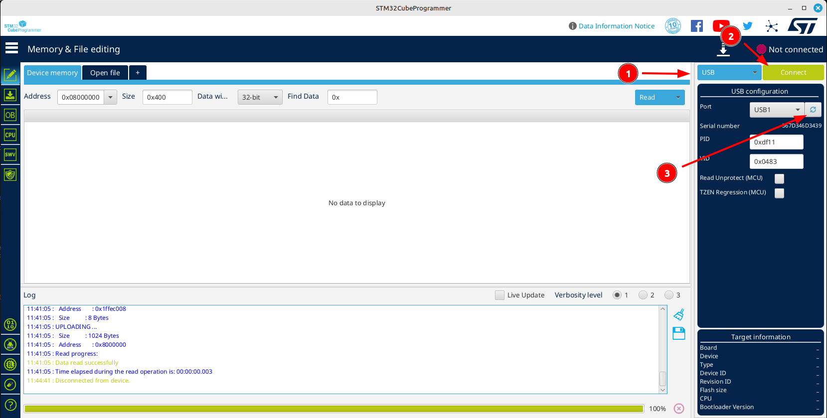
Убедитесь, что тип устройства (1) задан как USB, затем нажмите на кнопку Connect (2). Если поле Port пустое, попробуйте нажать на кнопку обновления (3). -
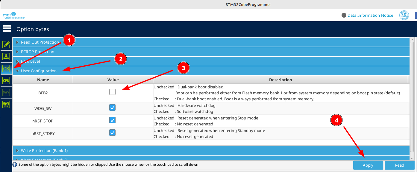
Перейдите на вкладку "Option bytes" (OB) (1). Затем раскройте раздел "User Configuration" (2). Проверьте статус конфигурационного бита "BFB2"3 (3). Если он отмечен галочкой, снимите её (как на картинке ниже) и нажмите кнопку Apply (4). После этого вы можете нажать кнопку "Disconnect" и отсоединить вашу аппаратуру от компьютера.
-
Если проблемы была вызвана значением бита BFB2, то теперь ваша аппаратура должна успешно включаться и работать.
-
-
Если вы подозреваете, что ваше устройство пришло в неработоспособное состояние ("окирпичено"), воспользуйтесь инструкцией how to unbrick your radio.
DFU (Device Firmware Update) - "Обновление прошивки устройства", специальный низкоуровневый режим работы аппаратуры, в котором все высокоуровневые функции отключены и контроль полностью передаётся внешнему устройству (компьютеру). Позволяет полностью перезаписать встроенное программное обеспечение.
Option Bytes (опционные байты) в STM32 — это специальные конфигурационные параметры, хранящиеся во флеш-памяти микроконтроллера. Они управляют важными настройками, такими как защита памяти (RDP), выбор источника тактирования, режим загрузки и поведение аппаратных интерфейсов. Изменение этих байтов позволяет, например, защитить прошивку от чтения или переключить микроконтроллер в альтернативный режим работы. Изменять их нужно осторожно, особенно параметры RDP и WRP.
Бит BFB2 (Boot From Bank 2) в опционных байтах STM32 отвечает за выбор банка памяти, из которого загружается прошивка. При обновлении устройства с поддержкой двойного банка (Dual-Bank Flash) можно записать новую прошивку во второй банк, а затем переключить BFB2, чтобы после перезагрузки загрузка происходила уже из обновлённого банка, обеспечивая безопасное обновление без риска "окирпичивания". Этот бит актуален для STM32 с двойной банковой флеш-памятью (например, STM32F7, STM32H7), где прошивка может находиться в двух независимых банках, и можно переключаться между ними без стирания памяти.
User Manual for Color Screen Radios
Примечание: пока перевод раздела 4 не окончен, воспользуйтесь документом Руководство пользователя для аппаратур управления с цветным дисплеем от Руслана Кергет
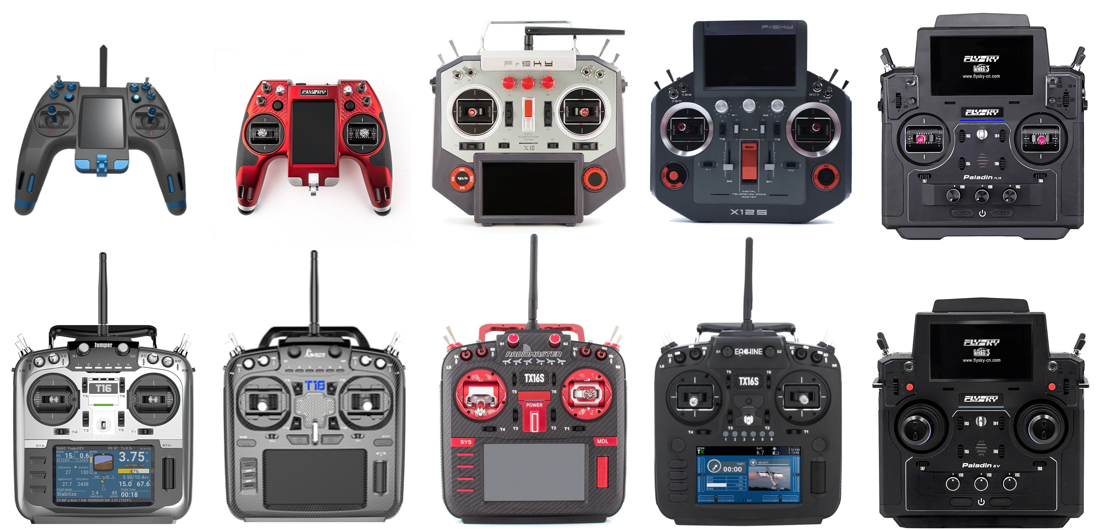
EdgeTX supported color screen radios
EdgeTX supports the following color screen radios:
- FlySky NV14 / EL18
- FlySky PL18 / PL18 EV
- FrSky X10 / X10S / X10 Express / X10S Express
- FrSky X12S / X12S-IRSM
- Jumper T15
- Jumper T16 / T16 Plus / T16 Pro Hall
- Jumper T18 / T18 Lite / T18 Pro
- RadioMaster/Eachine TX16S / RadioMaster TX16S MAX / RadioMaster TX16S Mark II
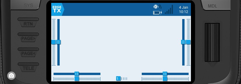
User Interface
The user interface of EdgeTX can be navigated by physical buttons, the touch interface, or a combination of both.
Common buttons for navigation
Buttons:
-
[SYS] - System Button
- Short press [SYS] button to go to the Radio Settings page.- Long press the [SYS] button to go to the Radio Setup page.
-
[MDL] - Model Button
- Short press [MDL] button to go to the Model Settings page
- Long press [MDL] button to go to the Select Model page -
[RTN] - Return / Back
- Short press [RTN] button to return to the previous page, previous menu or cancel action -
[PAGE>] / [PAGE<] - Page next & page previous
- Used to navigate between different screens, tabs, or options settings, depending on the screen. -
[TELE] - Telemetry
- Short press the [TELE] button to go to the Screen Settings page-Long press the [TELE] button to go to the Channel Monitor page
-
[Roller] or [Dial] - Next & previous value
The roller is used to navigate through menu options. -
[Enter] - Accept
- Used to select option, function or accept value
- Push [Roller] or [Dial] button to select or enter.
Additional System and Model button functionalities
The system and model buttons have different functionalities based on what screen you are in the user interface:
In the Radio Setup screen:
- Short press [MDL] navigates to the Model Setup screen
- Long press [MDL] navigates to Manage Models screen
In the Model Setup screen:
- Short press [SYS] navigates to the Radio Setup (TOOLS) screen
- Long press [SYS] navigates to the Radio Setup (SETUP) screen
- Short press [MDL] navigates to the Channel Monitor (existing function)
- Long press [MDL] navigates to the Manage Models screen
In the Channels Monitor screen:
- Short press [MDL] navigates to the Model Setup screen
- Long press [MDL] navigates to the Manage Models screen
- Short press [SYS] navigates to the Radio Setup (TOOLS) screen
- Long press [SYS] navigates to the Radio Setup (SETUP) screen
In the Manage Model screen:
- Short press [MDL] navigates to the Model Setup screen
- Short press [SYS] navigates to the Radio Setup (TOOLS) screen
- Long press [SYS] navigates to the Radio Setup (SETUP) screen
Touch Interface:
Certain radios are equipped with a touch screen. On these radios, you can interface with the menu options either with touch or physical buttons.
Touch the EdgeTX icon in the upper left corner of the screen to open the main navigation menu. Touch the desired menu option to select it.
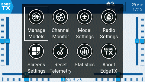
Main navigation menu
Pressing the roller from the main screen will also open the main navigation menu. You can then scroll using the roller to the desired menu option and select it by pressing the roller.
Virtual Keyboards
To allow for the easy entry of text and numbers, EdgeTX uses virtual text and number keyboards that can be interacted by either the touchscreen or roller. Additionally, there are shortcut keys that are mapped to the hardware buttons as described below:
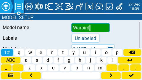
Virtual Text Keyboard
Shortcuts to the text keyboard using the hardware keys.
Radios with a single PGUP/DN keys and the X12S:
- [SYS] = cursor left
- LONG [SYS] = cursor to start
- [MDL] = change keyboard mode (alpha upper, alpha lower, numbers + special, numeric)
- LONG [MDL] = backspace
- [PGDN] = toggle case
- [PGUP] (X12S) = toggle case
- LONG PGDN = delete
- [TELE] = cursor right
- LONG [TELE] = cursor to end
Radios with separate PGUP and PGDN keys:
- [SYS] = change keyboard mode (alpha upper, alpha lower, numbers + special, numeric)
- LONG [MDL] = backspace
- [PGDN] = cursor right
- LONG [PGDN] = cursor to end
- [PGUP] = cursor left
- LONG PGUP = cursor to start
- [TELE] = toggle case
- LONG [TELE] = delete
Virtual Number Keyboard
Shortcuts to the number keyboard using the hardware keys.
Radios with a single PGUP/DN keys and the X12S
- [SYS] = '-'
- LONG [SYS] = 'MIN'
- [MDL] = '>>'
- LONG [MDL]= '+/-'
- [PGDN] & [PGUP] = '<<'
- LONG [PGDN] & [PGUP] = 'DEF'
- [TELE] = '+'
- LONG [TELE] = 'MAX'
Radios with separate PGUP and PGDN keys:
- [SYS] = '<<'
- LONG [SYS] = 'MIN'
- [MDL] = '>>'
- LONG [MDL] = 'MAX'
- [PGDN] = '+'
- [PGUP] = '-'
- [TELE]= '+/-'
- LONG [TELE] = 'DEF'
description: Navigating the menus with Trim hat switches on NV14 & EL18
Trim Navigation
On the NV14 and EL18 radios, it is possible to navigate the menu options using the Trim hat switches.
In the radio setup screen, you can configure the Hats Mode with one of the following options:
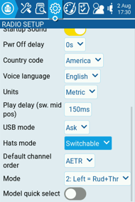
Hats mode option
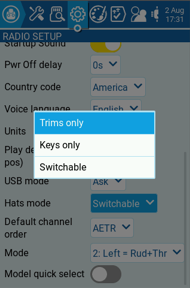
Configuration options
.png)
Hats mode help text
- Trims only: The Trim hat switches will be used to adjust the trim values only.
- Keys only: The Trim hat switches will be used to navigate the menu options (as described below)
- Switchable: Trim hat switch functionality can be changed between Trims and Keys on-the-fly.
.png)
Keys mode
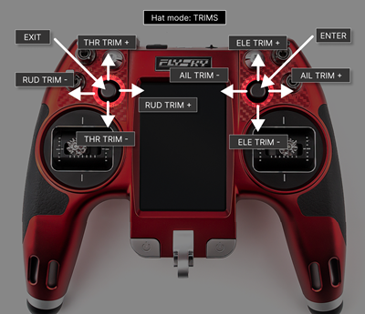
Trims mode
To switch between modes on-the-fly
- Configure Hats Mode as Switchable.
- Press and hold the Left Hat.
- Immediately after, press the Right Hat.
Manage Models
The Manage Models screen allows you to create new models, select which model is active, create and apply model labels, and create model templates.
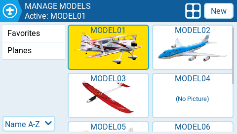
Manage Models screen
Selecting & managing existing models
The active model's name will be highlighted (yellow in this case) and displayed on the screen's top bar. Double-tapping an active model will give you the following options:
- Duplicate model - This option creates an exact duplicate of the model with the same name. Changes to the model name or other settings need to be made in the Model Settings tab.
- Label Model - When this option is selected, all configured labels will be displayed and can be selected for this model. More Information about Model Labels is below.
- Save as template - this option saves a copy of the model as a model template.
Double-tapping on a non-active model (unhighlighted) will give you the following options:
- Select model - this option selects this model as the active model.
- Duplicate model - same as described above.
- Delete model - this option moves the model to the deleted folder on the SD Card. Only models that are not active can be deleted.
- Label model - same as described above.
- Save as template - same as described above.
Creating a new model
To create a new model, select the New Model button in the upper right corner. You will then be presented with the following options:
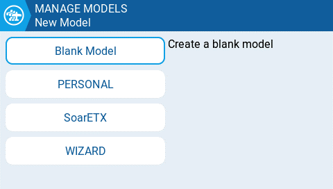
New model options
- Blank Model - This will create a blank model with only the default options configured.
- PERSONAL - This option will allow you to select one of your saved model templates and then create a copy of it as a new model.
- SoarETX - This will display pre-configured model templates for radio-controlled model sailplanes.
- WIZARD - This will launch the new model wizard and create the model as configured in the wizard.
Model Labels
Model labels allow you to give each model one or more labels. You are then able to filter the models displayed in the Manage Models screen based on the labels that you select. This allows people with many configured models to find them easier. By default, the Favorites and Unlabeled labels are created automatically. All models are considered unlabeled until a label is applied to them.
Filtering models using labels
To filter the visible models based on their labels, select the filter or filters from the left column. It will automatically filter out the models that do not have those model labels. For more information on how the filters work or to configure advanced filtering options, see: Additional Radio settings
Assigning labels to models
To assign a label to a model, double-tap on the model or press [Enter] when the model is selected and then select Label Models. Once selected, all configured labels will be displayed and one or more labels can be selected for this model. Labels applied to the model will be designated with a check icon.
Creating new model labels
To create a new model label, select the New button on the bottom left of the screen. The Enter Label pop-up will appear and you can enter the desired label name. Select Save to save the new label.
Editing model labels
Long press [Enter] or long tap on desired label and you be shown a menu with the following options:
- Rename Label - change the label's name
- Delete Label - Deletes the label from the label list and from all models that have it assigned.
- Move Up - positions the label higher on the list
- Move Down - - positions the label lower on the list
Sorting models
The drop-down menu below the label list is for sorting the filtered models. Models can be sorted as described below:
- Name A-Z
- Name Z-A
- Least Used
- Most Used
Selecting the layout for the model list
There are 4 layouts for the model list in the Manage Models page:
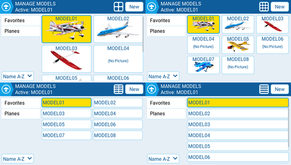
Model List Layouts
- Large image (2x2) - Default layout
- Small image (3x3)
- Name only, 2 columns (2x6)
- Name only, 1 column (1x6)
The layout can be changed by pressing the Layout button (next to the New button), which will cycle through the available layouts.
Model Settings
.png)
The Model Settings screen contains all the options to configure your model. Across the top of the page you will see icons that will take you to different pages of model settings when selected. The default screen for model settings is themodel-setup screen.
The icons at the top of the screen include (in order from left to right):
- Model Setup
- Heli Setup
- Flight modes
- Inputs
- Mixes
- Outputs
- Curves
- Global Variables
- Logical Switches
- Special Functions
- Telemetry
description: General model settings
Model Setup
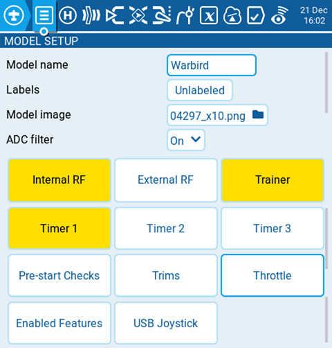
Model Setup tab under Model Settings
The model setup page is the default page for model settings and is where you start to configure your model. It contains the following settings:
Model name
Enter the desired name for the model. The maximum number of characters is 15.
Labels
Here you may assign a label from your defined label list. By default, the model label will be Unlabeled. More information on creating labels can be found on the select-model.md page.
Model image
When the folder icon is selected, a window will pop up allowing you to select an image file from the images folder on your SD Card.
ADC Filter
Enables/disables the ADC filter for this model. The global option will take the value designated in the radio settings, which is on by default.
Internal / External RF
The configuration settings for both the Internal and External RF pages work the same. The only difference is that the Internal RF section is for configuring the built-in module and the External RF section is for configuring an RF module in the external module bay.
The Internal / External RF modules are "active" for a model when the buttons are yellow and inactive when they are white.
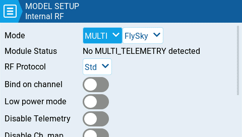
Internal RF with multi-protocol module selected
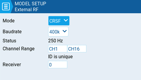
External RF with CRSF selected
Receiver number
The receiver number is a user-assigned number for a model that is sent to the receiver when bound. Each model must have a unique receiver number. However, models using different protocols may have the same receiver number without issues. EdgeTX will inform you when a receiver number is unique or if it is already being used with a text above the number field.
Mode Options
- Off - RF Module is not used
- PPM - Pulse position modulation, used by many generic JR compatible modules.
- Telemetry - No telemetry or MLink
- Channel Range - Channels that will be used.
- PPM Frame – Frame length, pulse length, and polarity of the PPM frame. The frame length is automatically adjusted to the correct value when the number of transmitted channels is changed. However, this automatically assigned value can be manual changed.
- XJT -
- Protocol- D16, B8, LR2
- Channel Range - Channels that will be used.
- Failsafe Mode - Available in D16 protocol. The receiver will use this setting when the transmitter signal is not being received (signal loss).
- Not Set - failsafe mode is not set.
- Hold – The receiver keeps channel values at their last received state from the transmitter.
- No pulses – No PWM pulses are output.
- Receiver – Follows the fail-safe settings configured on the receiver. Follow the instructions that come with the receiver.
- Custom – The receiver changes the channel values to the custom set values.
- Custom Set – Each channel can have its own setting. The options are a value, hold and no pulses.
- Receiver Number - a user-assigned number for a model that is sent to the receiver when bound
- Bind - This puts the transmitter into bind mode. When in this mode the transmitter will make a chirp sound every 2.5 seconds.
- Range . This puts the transmitter into range check mode. When in this mode, the RSSI value is displayed and a sound is made every 5 seconds.
- DSM2
- Protocol - LP45, DSM2, DSMX
- Channel Range - Channels that will be used.
- Receiver Number - a user-assigned number for a model that is sent to the receiver when bound
- Bind - This puts the transmitter into bind mode. When in this mode the transmitter will make a chirp sound every 2.5 seconds.
- Range . This puts the transmitter into range check mode. When in this mode, the RSSI value is displayed and a sound is made every 5 seconds.
- CRSF
- Baud Rate - the speed to which the Transmitter module and the Radio Handset communicate.
- Status - Shows the packet radio configured on the trasmitter module.
- Channel Range - Channels that will be used.
- Receiver Number - a user-assigned number for a model that is sent to the receiver when bound
- Multi - Multiprotocol Module. The configuration options are unique to each selected protocol Configuration options for the multi-protocol module are described here: https://www.multi-module.org/using-the-module/protocol-options
- R9M
- Mode- FCC, EU, 868MHz, 915 MHZ
- Failsafe Mode - The receiver will use this setting when the transmitter signal is not being received (signal loss).
- Not Set - failsafe mode is not set.
- Hold – The receiver keeps channel values at their last received state from the transmitter.
- No pulses – No PWM pulses are output.
- Receiver – Follows the fail-safe settings configured on the receiver. Follow the instructions that come with the receiver.
- Custom – The receiver changes the channel values to the custom set values.
- Custom Set – Each channel can have its own setting. The options are a value, hold and no pulses.
- Receiver Number - a user-assigned number for a model that is sent to the receiver when bound
- Bind - This puts the transmitter into bind mode. When in this mode the transmitter will make a chirp sound every 2.5 seconds.
- Range . This puts the transmitter into range check mode. When in this mode, the RSSI value is displayed and a sound is made every 5 seconds.
- RF Power - The output power for the transmitter module. The options change based on the selected mode.
- R9M Access Note: In order for the mode R9M ACCESS to be visible in the mode dropdown**,** the AUX1 or AUX2 serial port must be configured to External Module on the Hardware page.
- Channel Range - Channels that will be used.
- Failsafe Mode - The receiver will use this setting when the transmitter signal is not being received (signal loss).
- Not Set - failsafe mode is not set.
- Hold – The receiver keeps channel values at their last received state from the transmitter.
- No pulses – No PWM pulses are output.
- Receiver – Follows the fail-safe settings configured on the receiver. Follow the instructions that come with the receiver.
- Custom – The receiver changes the channel values to the custom set values.
- Custom Set – Each channel can have its own setting. The options are a value, hold and no pulses
- Not Set - failsafe mode is not set.
- Module - Please refer to FrSky documentation for these configuration settings
- Register
- Range
- Options
- Register
- Receiver No (Number) - a user-assigned number for a model that is sent to the receiver when bound
- Bind - This puts the transmitter into bind mode. When in this mode the transmitter will make a chirp sound every 2.5 seconds.
- GHST - ImmersionRC Ghost
- Channel Range - Channels that will be used.
- Raw 12 bits - enable 12bit mode
- SBUS
- Channel Range - Channels that will be used.
- Refresh Rate - Rate of refresh in milliseconds
- Inversion - Normal, Non-inverted
- FLYSKY
- Protocol - AFHDS3, AFHDS2A
- Module Status - Status of the module
- Type - Please refer to FLYSKY documentation for these configuration settings
- Module Options- Please refer to FLYSKY documentation for these configuration settings
- Channel Range - Channels that will be used.
- Failsafe Mode - The receiver will use this setting when the transmitter signal is not being received (signal loss).
- Not Set - failsafe mode is not set.
- Hold – The receiver keeps channel values at their last received state from the transmitter.
- No pulses – No PWM pulses are output.
- Receiver – Follows the fail-safe settings configured on the receiver. Follow the instructions that come with the receiver.
- Custom – The receiver changes the channel values to the custom set values.
- Custom Set – Each channel can have its own setting. The options are a value, hold and no pulses.
- Receiver (number) - a user-assigned number for a model that is sent to the receiver when bound
- Bind - This puts the transmitter into bind mode. When in this mode the transmitter will make a chirp sound every 2.5 seconds.
- LemonRx DSMP
- Channel Range - Channels that will be used.
- Bind - This puts the transmitter into bind mode. When in this mode the transmitter will make a chirp sound every 2.5 seconds.
- Range . This puts the transmitter into range check mode. When in this mode, the RSSI value is displayed and a sound is made every 5 seconds.
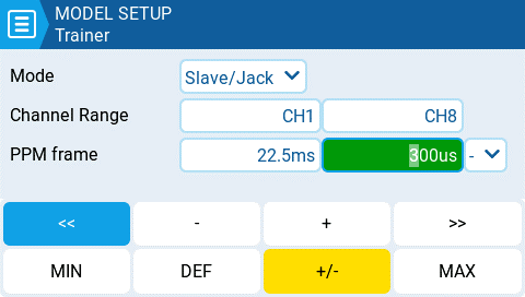
Trainer
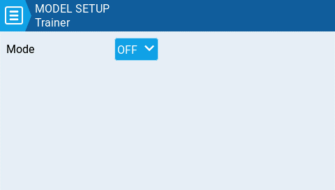
Trainer Screen
The Trainer screen is where you can configure the CPPM passthrough mode and method. When enabled, this allows the CPPM signals from a radio in Slave mode to be passed through to another radio in Master mode which will then pass the signal to the model it is connected to. CPPM passthrough can be used for several different use cases, such as: connecting a head tracker, Instructor / Student training mode, and controlling complex models that require more stick inputs than available on a standard transmitter.
Master mode - This is the mode for the radio that will be connected to the model. This radio also shall configure the special/global function (Trainer) to activate the passthrough mode. When the passthrough mode is activated, the CPPM signals from the radio in Slave mode will be sent to the model for control.
Slave mode - This is the mode for the radio that will pass it's CPPM values to the radio in Master mode, which are then sent to the model.
Below are the possibile configuration options:
- Off - Trainer mode is not used for this model.
- Master / Jack - Master mode using a cable connection.
- Slave / Jack - Slave mode using a cable connection.
- Channel Range - This is the range of channels that will be sent to the radio in Master mode. Channel 10 is the recommended last channel to use.
- PPM Frame - The first field is the length of the PPM frame. The second field is the stop length/delay between pulses. The dropdown is to select the polarity of the signal. The frame length is automatically adjusted to the correct value when the number of transmitted channels is changed. However, this automatically assigned value can be manual changed. Note: In most cases, the default setting does not need to be changed.
- Master / Bluetooth - Master mode using a Bluetooth connection (if installed in radio).
- Slave / Bluetooth - Slave mode using a Bluetooth connection (if installed in radio).
- Master / Multi - Master mode using an additional externally mounted Multi-protocol module for the connection. For more information on this setup, see set-up-wireless-trainer-with-mpm.md
Timer 1/2/3
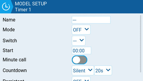
Timer configuration page
EdgeTX provides 3 timers that can be custom programmed. Below are the configuration options.
Name: Name of the timer
Mode:
- OFF- The timer is not used
- ON - The timer runs all the time
- Start -The timer starts once the configured switch is activated. After the time is started, the timer ignores the switch position.
- Throttle - The timer starts once the throttle is raised and the configured switch is activated. The timer will stop counting if either the throttle position is lowered back to the minimum value or the configured switch is deactivated.
- Throttle % - The timer counts proportionally to the throttle. It counts in real time at full throttle and at half speed at 50% throttle.
- Throttle Start - The timer starts once the throttle is raised and the configured switch is activated. After starting, the timer ignores the throttle position and will keep counting unless the switch is deactivated.
Switch- Select the switch that will trigger the timer to start. If no switch is selected, the timer will trigger based only on the configured mode. In addition to a switch, you can also select a trim, a telemetry source (triggered when telemetry data is received from that source), or physical activity (stick movement or button press) (labeled as ACT)
Start- The time used for the timer's advanced functions. The default value is 00:00 and when left as such, the timer operates like a stopwatch, counting upward until stopped. If a different time is entered in this box, then the additional Direction drop-down menu option will appear.
Direction - If set to Show Remaining, the counter will function like a countdown timer - counting down from the designated time to zero and then alerting the user. If set to Show Elapsed, the timer functions like an alarm, counting up from zero until the designated time and then alerting the user.
Minute Call - If selected, you will be notified every minute that passes as described in the Count Down option.
Count Down:
- Silent - No notification is given until the timer reaches zero. When it reaches zero, you will hear one beep.
- Beeps - The radio will beep every second starting at the time designated.
- Voice - The radio will count down by second starting at the time designated.
- Haptic -The radio will vibrate every second starting at the time designated.
- Beeps & Haptic - The radio will beep and vibrate every second starting at the time designated.
- Voice & Haptic - The radio will count down and vibrate by second starting at the time designated.
Persistent:
- Off - The timer value is reset when switching models or when the radio is turned off / on.
- Flight - The timer value is NOT reset when switching models or when radio is turned off / on. The timer value is only reset when the Reset flight option is selected in the Reset telemetry menu.
- Manual Reset - The timer value is reset only when it is individually selected to be reset (example: Reset timer1) in the Reset telemetry menu.
Pre-start Checks
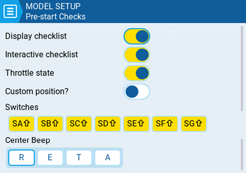
Pre-start Checks page
Whenever a new model is loaded, EdgeTX will conduct pre-flight checks based on the checks that are configured on this page. If any of the checks are failed, EdgeTX will give the user an audio and visual warning that must be acknowledged before using the model. The following preflight checks are configurable:
Display checklist - When this option is selected, the model notes file will be displayed when the model is loaded. A valid model notes file must be in the Models folder on the SD card. The model notes file must be a .txt file and must have the EXACT same name as the model it is for, for example: Mobula6.txt. The text in the file is up to the user.
Interactive checklist - This option is used with the Display checklist option. When this option is selected, any line of text in the checklist file that begins with = will display as a check box when the checklist is displayed. All displayed checkboxes must be checked by selecting them in order to close the checklist.
Throttle state - When selected, the radio will check that the throttle is at the minimum range value for the configured throttle source in the Throttle menu.
Custom Position? - When this option is selected, a number box will be shown that can be configured with a user-defined value for the throttle state check.
Switches - The section displays all the switches that are configured on the radio and allows you to select which position is the correct position for the switch state check. Selecting the switch will cycle through the available switch positions or turn the check off for the switch completely. Yellow switches have the switch position check activated. White switches e de-activated.
Pots & Sliders- When activated, this option checks the position of the pots & sliders. There are three options - OFF, ON and AUTO. When ON or AUTO is selected from the drop-down menu, buttons for the available pots and sliders will appear.
- OFF - Pot and slider positions are not checked.
- ON - Positions are checked against manually configured pot and slider positions that are set to active (yellow). To manually set the check position, select ON from the drop-down menu, put the pots and sliders into the desired position, and activate them by selecting them (yellow).
- AUTO - Positions are checked for activated pots and sliders and compared to the last automatically saved position before the radio was turned off or the model was changed.
Center Beep - Allows you to turn on / off the center beep function for the individual sticks, pots, and sliders by selecting them (yellow).
Trims
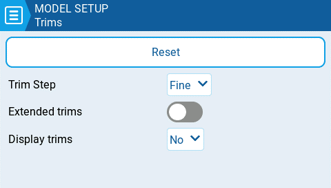
Trims settings page
Trims are used adjust the center position of a given stick axis. EdgeTX has the following time configuration options:
Reset - This resets all trim values to zero.
Trim Step: Defines the amount of increase/decrease in trim when the trim switch is pressed.
- Course = 1.6%
- Medium = 0.8%
- Fine = 0.4%
- Extra Fine = 0.2%
- Exponential = 0.2% near the center and the step value increases exponentially as the distance from the center increases.
Extended Trims: Increases the maximum trim adjustment value from **±**25% to **±**100%.
Display trims: Option to display the numerical trim value on the trim bar. Options are:
- No - Does not display the numerical trim value on the trim bar
- Yes - Displays the numerical trim value on the trim bar once the trim is no longer at zero.
- Change - Momentarily displays the numerical trim value on the trim bar (2 seconds) once the trim is no longer at zero.
Throttle
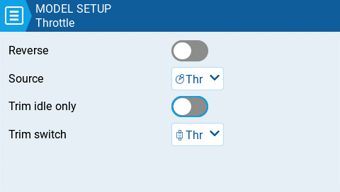
Throttle page settings
EdgeTX has to possibility to select a specific source and trim for the model throttle and allows for the following configuration options:
Reverse: When enabled, this option reverses the output direction of the configured throttle channel.
Source: The source that will be used for the throttle.
Trim idle only: When enabled, the throttle trim will only affect the bottom portion of the throttle band.
Trim switch: The trim switch that will be used to trim the throttle. It is possible to substitute the throttle trim switch with the aileron, rudder, or elevator trim switches.
Enabled Features
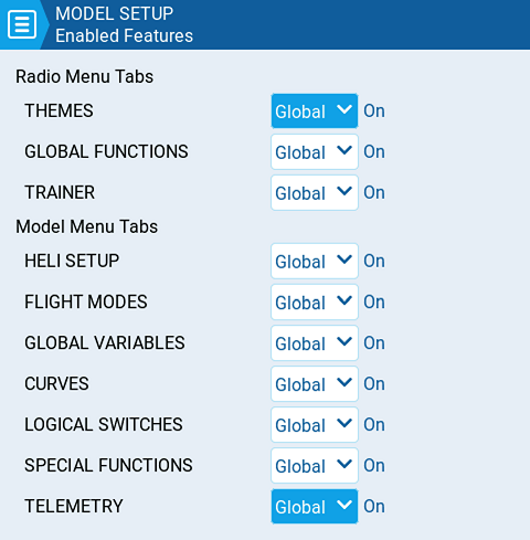
Enabled Features
The Enabled Features section of Model Setup allows you to configure which tabs are visible in the selected model's radio setup and model settings area of EdgeTX. You can select the following options:
- Global - When selected, the tab will take the global value configured in the Enabled Features area in Radio Setup. The configured global value will display next to the option.
- On - When selected, this tab will be visible when this model is loaded.
- Off - When selected, this tab will not be visible when this model is loaded.
EXCEPTION: Turning off the Global / Special Functions tab will disable configured global / special functions for that model.
USB Joystick
The USB Joystick has two possible modes, Classic and Advanced.
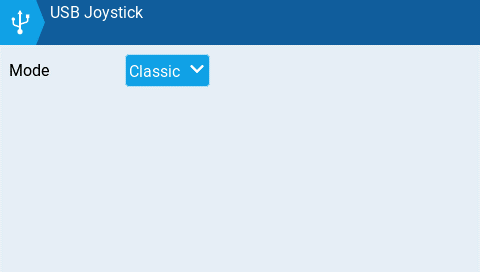
USB Joystick Classic mode
In Classic mode, the radio's configured output channels will be sent to the target device in numerical order and mapped to the device's preconfigured USB controller axes and buttons. Below is the default channel mapping for Microsoft Windows.
- Ch1 - X Axis
- Ch 2 - Y Axis
- Ch 3 - Z Axis
- Ch4 - X Rotation
- Ch 5 - Y Rotation
- Ch 6 - Z Rotation
- Ch 7 - Dial
- Ch 8 - Slider
- CH 9 - Ch 32 - Buttons 1 - 24
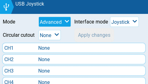
USB Joystick Advanced mode
In Advanced mode you can configure the following options:
Interface mode: This indicates to the target device (the device you are connecting your transmitter to) what type of device you are connecting. The options are Joystick, Gamepad, MultiAxis.
Circular cutout: For axis pairs (X-Y, Z-rX): By default, the range of the axis pairs is a rectangular area. With this option, the axis will be limited to a circular area (like gamepad controllers commonly are). Options are : None or X-Y, Z-rX or X-Y, rX-rY or X-Y, Z-rZ
Output channels 1-32
Mode: For each output channel, you can select the mode that you want to use for that channel. The available options are None, Btn, Axis, Sim.
None - Channel is not used
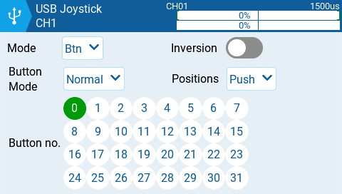
Button mode options for a selected channel
Btn - Channel is used to simulate a button. Configuration options include:
- Inversion - Inverts the output channel signal. Options are: On / Off
- Button Mode -
- Normal - Each postion of a multiposition switch is represented by a button. The current switch state is represented by a continous button press.
- Pulse - Similar to "Normal" mode. However, instead of continous button press it is represented by a short button press.
- SWEmu - The toggle switch emulations a push button. The first press turns the virtual button on, the second press turns it off.
- Delta - The change of the output channel is represented by 2 buttons. While the output value is decreasing, the first button is pressed. When the output value is increasing, the second button is pressed. If there is no change, then no buttons will be pressed.
- Companion - This option should be selected when using your transmitter to control the simulator in EdgeTX Companion. It allows the multi-position switches to function properly in the simulator.
- Positions - The type of button that will be simulated.
- Push - will only map to one button
- 2POS - 8 POS - will map to the number of buttons that the switch has (ex: 3POS will map to 3 buttons).
- Button No: The button number that the output will be mapped to and sent to the target device as.
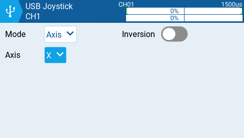
Axis mode options for a selected channel
Axis - The channel is used to simulate an axis and will be mapped to one of the target device's default axes.
- Axis options are: X, Y, Z, rotX (rotation x), rotY, rotZ

Sim mode options for selected channel
Sim - The channel is used to simulate a common sim axis and it will be listed on the target device as the selected option (ex: Thr)
- Sim Axis options are: Ail, Ele, Rud, Thr, Acc, Brk, Steer, Dpad
Heli Setup
The Heli Setup page in Model Settings is an optional page that is available on custom-compiled versions of EdgeTX. The heli setup page is often used for collective pitch mixing (CCPM) used in flybared helicopters where the receiver directly controls the swashplate servos. Most flybarless helicopters do not need to configure this page. The outputs of the CCPM mixer are CYC1, CYC2, and CYC3, which need to be assigned to an output channel on the Mixes screen.
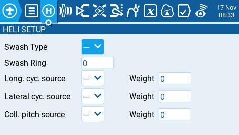
Heli Setup page
The heli setup page has the following configuration options:
- Swash Type - Swash type for your model. Options are 120, 120x, 140, and 90.
- Swash Ring - Set the swash ring limit only as needed. 1 = maximum limit -> 100 or 0 = no limit.
- Long. cyc. source - Select source input.
- Lateral cyc.source -Select source input.
- Coll. pitch source - Select source input.
- Weight - Percentage value of the stick travel to use.
Flight Modes
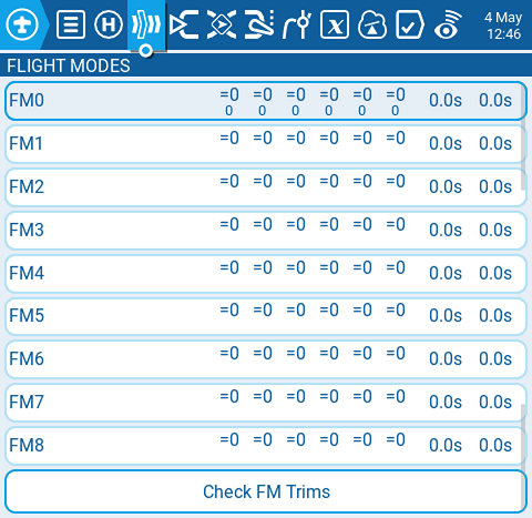
Flight Modes page
Flight modes allow you to have different trim settings for each flight mode. Once multiple flight modes are configured, you can adjust the trim settings in each flight mode without affecting the trim settings in other flight modes (unless they are configured to do so). There are 9 possible flight modes to use, with Flight Mode 0 being the default flight mode.
The Flight Mode screen displays an overview of each flight mode. The highlighed flight mode designates the active flight mode. Selecting a flight mode will take you to the configuration page for that flight mode.
Check FM Trims: When the check FM trims button is pressed, the trims for the current flight mode are temporarily disabled. This is used to test the impact of the current flight mode’s trims on the outputs.
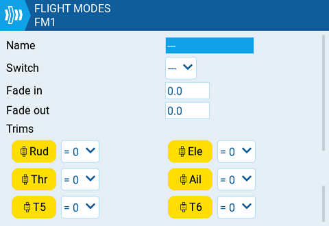
Flight Mode configuration page
The flight mode conifiguration screen has the following options:
Name: The custom name for the flight mode. If configured, this name will be shown on the lower center position of the main screen between the trims.
Switch: The trigger to enable that flight mode. It can be a switch, pot, telemetry, trim or logical switch.
Fade in: Gradually change the trim value when this flight mode is enabled. Specify the time in seconds (0.0 - 25.0) until the value change is completed.
Fade out: Gradually change the trim value when this flight mode is disabled. Specify the time in seconds (0.0 - 25.0) until the value change is completed.
Trims: To configure the trims, select the trim that you want to configure to make sure that it is turned on (yellow). Then select the flight mode (0-8) that will provide the initial trim value and modifier (= or +) from the drop-down menu. When 3P is selected instead of the flight mode (0-8), the trim will act as a 3 position momentary switch.
Modifier - there are two possible value modifiers = and +. The = modifier uses the trim value directly from the selected flight mode. The + modifier uses the trim value from the selected flight mode and then adds the trim value from the flight mode you are configuring.
Example 1: If you are configuring FM1 and set the value to =0, FM1 will have the trim value of the current value of the same trim in FM0. In this case, changes made to the trim in FM1 will also affect the trim in FM0 and vice-versa.
Example 2: If you are configuring FM1 and set the value to +0, FM1 will have the trim value of the same trim in FM0, plus any trim changes made while in FM1, In this case, changes made to the trim in FM1 do not affect the trim in FM0. However, changes to trim values FM0 will affect trim values in FM1.
Inputs, Mixes & Outputs
To be able to support many different types of radio transmitters, EdgeTX uses a generic control data flow that can be applied to any radio transmitter. In this data flow, any of the radio's physical controls (sticks, switches, sliders, pots) can be mapped to an input in the software. These inputs can be directly assigned or combined with other inputs into a single mix. These mixes can be modified by applying weights, offsets, and curves and are then assigned a channel for output. Final adjustments to the control data are made (including subtrims, curves, endpoint, and center values) before finally sending the control data to the RF module. The flowchart below depicts a visual summary of this control data flow. Detailed information about the flow is provided in the following sections Inputs, Mixes, and Outputs.
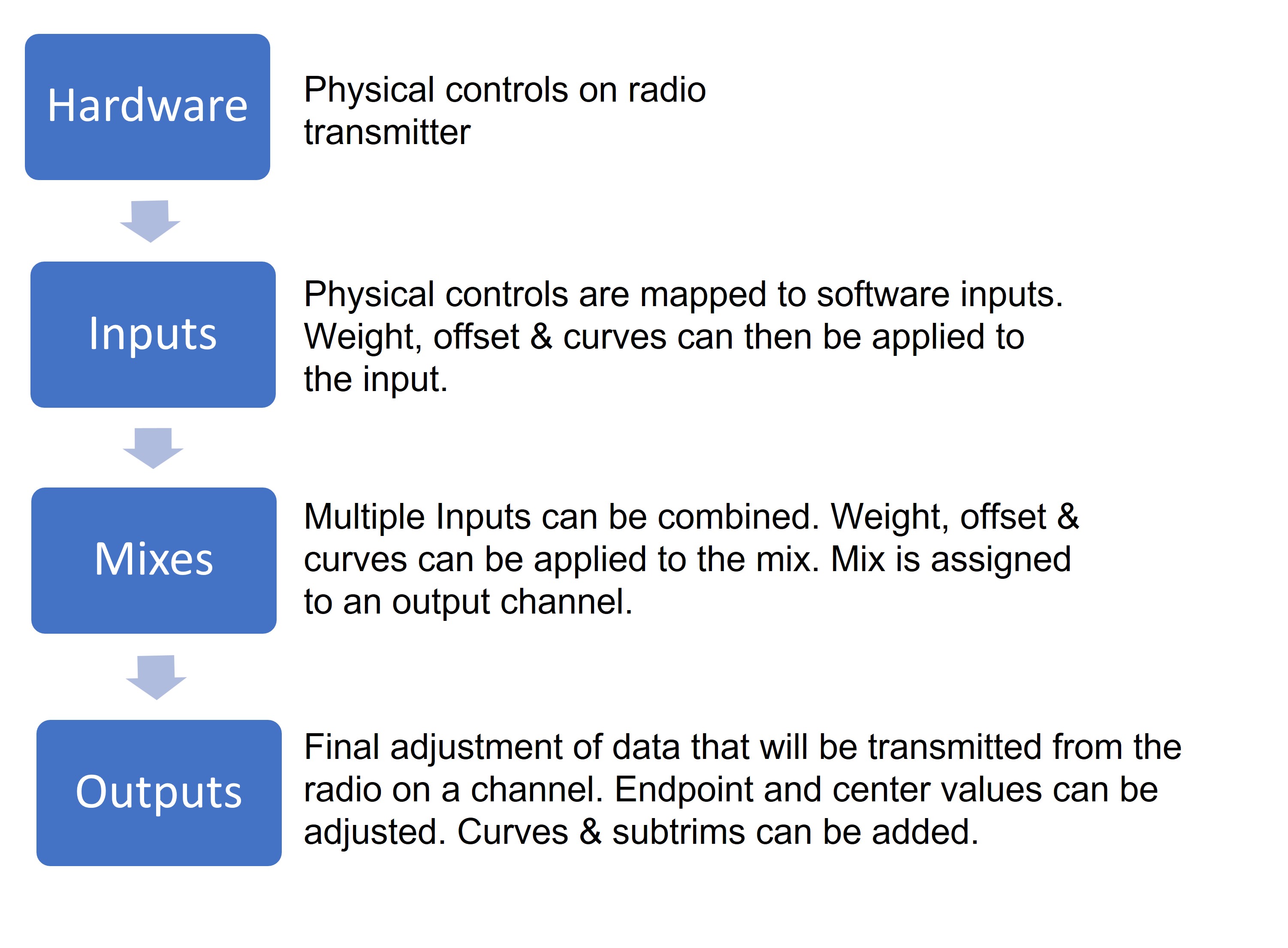
Control data flow
EdgeTX uses the icons below to designate different types of sources.
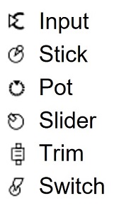
Source Icons
Inputs
The Inputs screen of Model Settings is where you map your physical radio controls (for example: sticks, sliders, and pots) to a software input to be used by the radio. After the control has been mapped it is then possible to apply modifiers to the inputs such as a weight, offset or curve which will then be applied anywhere that input is used. Although it is possible to also assign switches as inputs, it is normally not needed as switch outputs seldomly need to be modified by a weight, offset or curve. By default, EdgeTX will automatically map your contoller sticks to Aileron, Elevator, Throttle, Rudder based on the default channel order defined in Radio Setup.
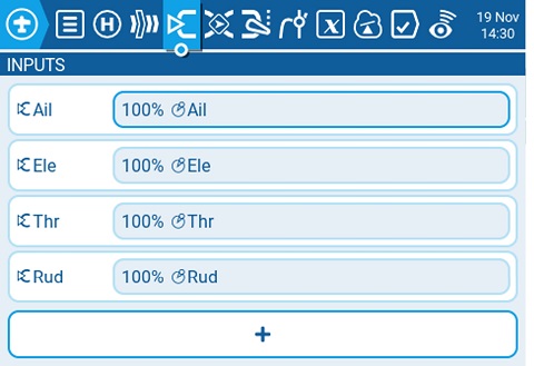
Inputs screen in Model Settings
Selecting the + button will show you a list of available inputs that can be configured. After selecting an input, the input configuration page for that input will open. Selecting an existing input will give you the following options:
- Edit - opens the input configuration page for that input line.
- Insert before - Inserts a new input line before the selected input.
- Insert after- Inserts a new input line after the selected input.
- Copy - copies the selected input line.
- Move - selects the input line to be moved. The input is moved using one of the paste commands after a new line is selected (i.e. cut & paste).
- Delete - deletes the selected input line.
- Paste before - pastes the copied or moved input line before the selected input line.
- Paste after - pastes the copied or moved input line before the selected input line.
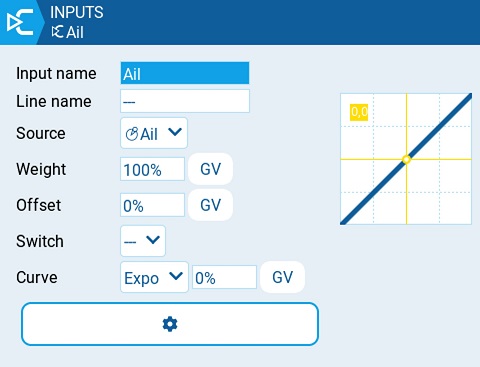
Input Configuration Page
Input configuration page
The input configuration page allows you to edit the input configuation parameters. To the right of the configuration parameters, you can see a live graph that shows how your configuration options will affect the slope of the input.
- Input Name - Name for the input. Four character are possible.
- Line Name - Name of the individual line in the input. Multiple physical inputs can be mapped to one input by adding an additional input line under the input.

Example of multiple input lines under one input
- Source - The physical control used for the input. In addition to physical controls, you can also specify MAX (always returns 100), MIN (always returns -100), cyclics, trim switches, channel values and more. Moving the physical control after the source has been selected will automatically map it to that input.
- Weight - Percentage value of the stick travel to use (often referred to as "rates").
- Offset - The value added to or subtracted from the input source.
- Switch - The switch that activates the input line. If no switches are defined then it is always active.
- Curve - Specifies the type of curve that will be used. The following curve options exist:
-
Diff - Multiplies only the range above or below the middle (0) by the specified %.
-
Expo -The input value is changed exponentially. Increasing the % will result with a gentle slope near the middle(0). Decreasing the % will result in a steep slope near the middle (0). With a % of 0, the slope will be linear.
-
Func -
Function Slope Behavior --- The slope will be linear. X>0 The range below the middle (0) is always 0. Above the middle (0), the slope is linear. X<0 The range above the middle (0) is always 0. Below the middle (0), the slope is linear. |X| The range above the middle (0), the reaction is linear. The sign is inverted in the range below the middle (0). The curve draws a V-shaped graph. f>0 The range above the middle (0) is always +100. The range below the middle (0) is always 0. The output value will always be either 0 or +100. f<0 The range above the middle (0) is always 0. The range below the middle (0) is always -100. The output value will always be either 0 or -100. |f| The range above the middle (0) is always +100. The range below the middle (0) is always -100. The output value will always be either +100 or -100. -
Cstm - assigns a custom defined curve. See Curves for more information about custom defined curves.
-
When selecting the gear button at the bottom of the screen, the following option window will be displayed.
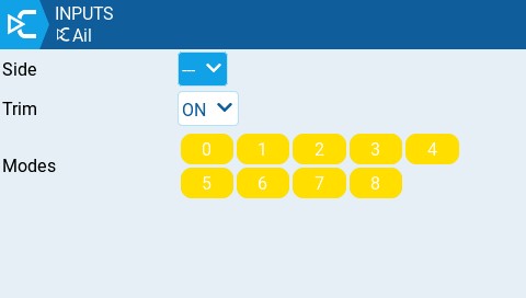
Side - Specifies the input range for which this line setting is valid. If you select ---, it will be valid in the entire range of Source values. If you select x>0, it will be valid in the upper half of the value of Source. If you select x<0, it will be valid in the lower half of the value of Source.
Trim - Specifies whether or not to include the trim values in this input. Additionally, you can select a different trim to use for this input.
Modes - Specifies which flight modes this input is active for.
Mixes
The Mixes screen of Model Settings is where several Inputs can be combined into one "Channel Mix". These mixes are then assigned to a radio channel for output. This is also the place where switches, knobs or sliders are assigned to a channel for output. Similar to the Input section, it is also possible to assign a weight, offset or curve to a channel mix.
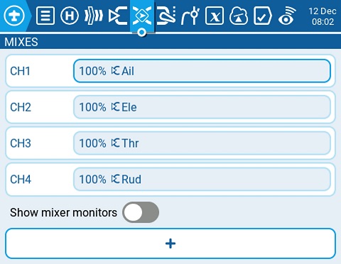
Mixes Page
Selecting the + button will create a new mix and open the mixes configuration page. Selecting an existing mix will give you the following options:
- Edit - opens the mixes configuration page for that mix line.
- Insert before - Inserts a new mix line before the selected mix.
- Insert after - Inserts a new mix line after the selected mix.
- Copy - copies the selected mix line.
- Move - selects the mix line to be moved; mix is moved using one of the paste commands after a new line is selected (i.e. cut & paste).
- Delete - deletes the selected mix line.
- Paste before - pastes the copied or moved mix line before the selected mix line.
- Paste after - pastes the copied or moved mix line before the selected mix line.
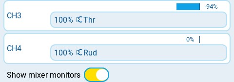
Mixes with Show Mixer Monitors enabled
Show mixer monitors - Selecting this option will display a bar graph on the mix channels showing the current value for that mix channel.
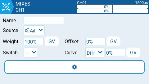
Mixes configuration options
The upper right portion of the mixes configuration page contains a channel monitor for the selected mix line. It shows the output (top) and mix (bottom) values. The following configuration options are also available:
- Name - Name of the mix (optional). Up to 6 characters are allowed.
- Source - The source for the mix. In addition to inputs, you can select sticks, pots, sliders, trims, physical and logical switches, heli mixer outputs, trainer import channel values, and other channels.
- Weight- Percentage of the source value to use.
- Offset - The value added to or subtracted from the source.
- Switch - The physical switch that activates this mix line (optional). If no switch is selected, then the mix will be active by default.
- Curve - Specifies the type of curve that will be used. See the curve section on the Inputs page for detailed explanations of the different curve types.
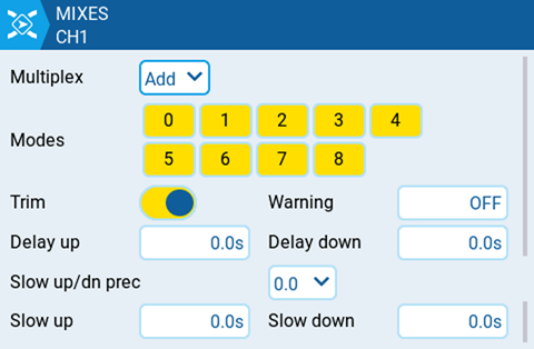
Additional Mixes settings
- Multiplex - The multiplex setting defines how the current mixer line interacts with the others on the same channel. Add will add its output to them, Multiply will multiply the result of the lines above it, and Replace will replace anything that was done before it with its output.
- Modes - Specifies which flight modes this mix is active for.
- Trim - Specifies whether or not to include the trim values in this mix. For the trim values to be included, the trim field for the relevant input must also be enabled on INPUTS screen.
- Warning -when selected, the radio will beep when this mix is active. You can choose from OFF (0) or beep patterns 1, 2, 3.
- Delay up - Creates a time delay in seconds between when the source value increases and when it is output.
- Delay down - Creates a time delay in seconds between when the source value decreases and when it is output.
- Slow up/dn pre (precision) - Changes the precision for Slow up/dn between 0.0 and 0.00.
- Slow up - Adjusts the transition speed for source value increases. Specify the time to transition from -100% to + 100% in seconds. You can specify a range from 0.00 seconds to 25.00 seconds.
- Slow down - Adjusts the transition speed for source value decreases. Specify the time to transition from -100% to + 100% in seconds. You can specify a range from 0.0 seconds to 25.0 seconds.
Outputs
The Outputs screen of Model Settings is where final adjustments to the control data are made (including subtrims, curves, endpoint, and center values) before finally sending the control data to the RF module. This is where the channel center, limits (to prevent servo binding) and output direction are set.
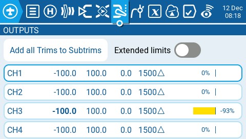
Outputs screen
The output screen shows all the configured output channels. For each output line, it displays the values for the minimum and maximum limits, subtrim, center point, subtrim mode and channel monitor. The two options below are also available on the output page:
- Add all Trims to Subtrims - When selected, adds the current trim value to the subtrim value for each configured output. The trim value is then reset to zero.
- Extended Limits - When enabled, it increases the minimum and maximum range for the output values to -150 and 150. Extended limits are necessary if the full range of the control surface cannot be reached with standard limits.
Selecting an output line will give you the following options:
- Edit - Opens the output configuration screen.
- Reset - Sets the subtrim value back to zero. The trim value is not changed.
- Copy Sticks to Subtrim - Adds the current value of the stick deflection as the subtrim value.
- Copy Trims to Subtrim - Adds the current trim value to the subtrim value. The trim value is not changed.
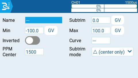
Outputs Configuration page
The output configuration screen has the following configuration options:
- Name - Name for the Output up to 6 characters.
- Subtrim - The subtrim value (max 100). It can also be set to a global variable by pressing the "GV" button and then selecting the desire global variable from the dropdown menu.
- Min - Minimum output limit. Commonly used to prevent servo binding on models that use servos for the control surfaces.
- Max - Maximum output limit. Commonly used to prevent servo binding on models that use servos for the control surfaces.
- Inverted - Select this option if you want to invert the output value.
- Curve - Specify the custom curve (in any) that you want to use for this output. See Curves for more information about custom defined curves.
- PPM Center - Specify the pulse-width value for the center value of the output channel (between 1000 - 2000). Changing this will shift the entire output range, including upper and lower limits.
- Subtrim mode - Defines how the subtrim value affects the min/max output values. There are two options:
- Center Only - Only the center value shifts and the upper and lower limits do not change. The reaction of the stick differs between the upper half and the lower half from midpoint.
- Symmetrical - the upper and lower limits will shift according to the shift of the center value. The reaction of the stick is the same on both sides of the midpoint.
Curves
The Curves screen of Model Settings allows you to define custom curves to use in the Inputs, Mixes, or Output screens. The curves screen will show all of the configured custom curves, with a graphical representation of each curve, the number of points, and the curve type.
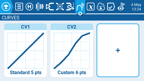
Curves screen
Selecting an existing custom curve will display the following options:
- Edit - Opens the curve configuration page.
- Preset - Allows you to set the curve to one of the preset slope values (-45 to 45 degrees in 15 degree increments). The curve will have 5 points and smoothing is not enabled by default.
- Mirror - Mirrors the selected curve.
- Clear - Clears all curve values from the selected curve.
Selecting the plus button to create a new curve will give you the following options:
- Edit - Opens the curve configuration page.
- Preset - Allows you to set the curve to one of the preset slope values (-45 to 45 degrees in 15 degree increments). The curve will have 5 points and smoothing is not enabled by default.
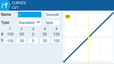
Curve configuration screen
Selecting Edit for a configured or unconfigured curve will open the curve configuration screen and display the following options:
- Name - Name for the curve. Only 3 characters are possible.
- Type - Type of curve: Options are Standard and Custom
- Standard - Horizontal axis points are fixed values based on the number of points. Vertical axis points are adjustable.
- Custom - Both horizontal and vertical axes are adjustable.
- Number of Points - number of points in the curve
- Smooth - When enabled, connects the points with curved lines instead of straight lines
- Verticle point values - Adjust the point values to make the desired curve.
Global Variables
Global variables are variables whose values are shared across all the configuration screens of a model. Their values can be used in weights, offsets, differential, expo settings, outputs, and in logical switch comparisons. The Global Variables screen of Model Settings shows the value of each global variable for each flight mode.
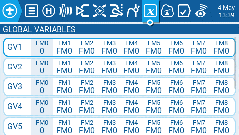
Global variables screen
Selecting a global variable from the global variable screen will give you the following options:
- Edit - Opens the global variable configuration screen for the selected global variable.
- Clear - Clears the global variable values for all flight modes for the selected global variable.
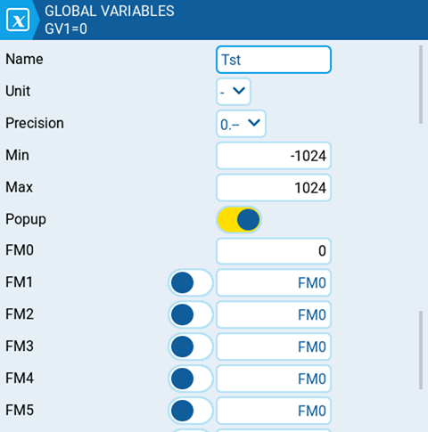
Global Variable configuration screen.
The global variable configuration screen is where you assign a value and other configuration options to a global variable. Additionally, you can select how the value of the global variable is defined for every flight mode - either the value is manually defined or inherited from another selected flight mode. It contains the following configuration options:
- Name - Name for the global variable. Three characters are allowed. If left blank, it will use the default GV# as the name.
- Unit - (optional) Allows you to add a % label to the displayed values when selected. It DOES NOT affect how the values are calculated.
- Precision - Allows you to select the number precision options whole numbers (0.-) and decimal (0.0). The default value is 0.-
- Min - Defines the minimum that is allowed for the global variable.
- Max - Defines the maximum value that is allowed for the global variable.
- Popup - When enabled, a popup message will be displayed when the value of a GV changes with the new GV value (see image below).
- FM0 - The value of the global variable on Flight Mode 0.
- FM1 -> FM8 - When the toggle switch is enabled or disabled, the following applies:
- Toggle switch disabled - global variable value for the selected flight mode is inherited from the flight mode defined in the drop-down.
- Toggle switch enabled (highlighted) - the global variable value for the selected flight mode is manually defined in the text field.
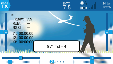
Popup message of global variable change
Logical Switches
Logical Switches are virtual two-position switches whose values (ON/OFF or +100/-100) are based on the evaluation (true/false) of a defined logical expression. Once configured, logical switches can be used anywhere in EdgeTX that a physical switch can be defined.
The Logical Switches page in Model Settings shows you all the configured logical switches as well as an overview of their configured options.
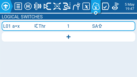
Logical Switches screen
Selecting the + button will allow you to select an unused logical switch to configure.
Selecting a configured logic switch will give you the following options:
- Edit - Opens the Logical Switches configuration page for the selected logical switch.
- Copy - Copies the selected logical switch
- Paste - Pastes a copied logical switch onto the selected logical switch. Note: it will overwrite the selected logical switch.
- Clear - Deletes all configuration options for the selected logical switch.
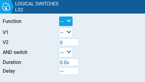
Logical Switches configuration screen
After selecting to edit a logical switch, you will have the following configuration options:
- Func - The logical function that you want to use. See Logical Switch Functions below for a description of the possible functions you can use.
- V1 - The first variable in the expression to evaluate.
- V2 -The second variable in the expression to evaluate.
- AND switch - Switch that must be active to allow the logical switch to be evaluated for activation.
- Duration - The duration that the logical switch will remain active (true) once meeting activation criteria. If set to 0.0, the the logical switch will remain active (true).
- Delay - Delay between when the activation criteria for the logical switch has been met and when the logical switch changes to the activated state (true).
Logical Switch Functions
In the expression, a and b represent sources (sticks, switches, etc.), and x represents the constants (values) to be compared.
| Expression | Description |
|---|---|
| a=x | True when the source V1 is exactly the same as the constant V2. |
| a~x | True when the source V1 is about the same as the constant V2. |
| a>x | True when the source V1 is greater than the constant V2. |
| a<x | True when the source V1 is less than the constant V2. |
| |a|>x | True when the absolute value of the source V1 is greater than the constant V2. |
| |a|<x | True when the absolute value of the source V1 is less than the constant V2. |
| AND | True when both sources V1 and V2 are TRUE. |
| OR | True when either source V1 or V2 is TRUE. |
| XOR | True when the source V1 and V2 positions do not match. |
| Edge | Momentarily true when the source V1 has been active for the defined period of time and then deactivated. The first time field (T1) under V1 is the minimum active duration required for source V1 to activate the logical switch. The second time (T2) is the maximum time allowed for the source V1 to be active for the logic switch to be activated. When T2 is set to --, the logical switch will be true regardless of how long V1 has been active. When T2 is set to 3, if V1 is active for more than 3 seconds, the logical switch will not be set to true when the source is deactivated. When T2 is set to <<, the logical switch will be true when the time conditions in T1 are met without source V1 being deactivated. |
| a=b | True when source V1 is the same as source V2. |
| a>b | True if source V1 is greater than source V2. |
| a<b | True if source V1 is less than source V2. |
| △>x | Momentarily true every time the source V1 changes by more than the amount indicated by the constant V2. |
| |△|>x | Momentarily true every time the absolute value of the source V1 changes by more than the amount indicated by the constant V2. |
| Timer | Momentarily true every xxx seconds. Argument V1 is the duration that the logical switch is true (active). Argument V2 is the time between logical switch activations. Repeats timer cycle as long as the defined switch is active. |
| Stky (Sticky) | "Sticks" true after switch V1 is active (true) and stays active (true) regardless of V1 position until switch V2 is activated (true) and "unsticks" or deactivates (false) the logical switch. |
Special Functions
The Special Functions section of Model Setup, as the name implies, is where you can configure the special functions that are included in EdgeTX. These special functions add additional functionality beyond normal model controls such as enabling trainer mode, playing a sound, adjusting the radio backlight, adjusting radio volume, etc. On the special functions screen you will see all configured special functions as well as some of the configured options such as function name, activation switch, if the function is enabled, and other configuration options.
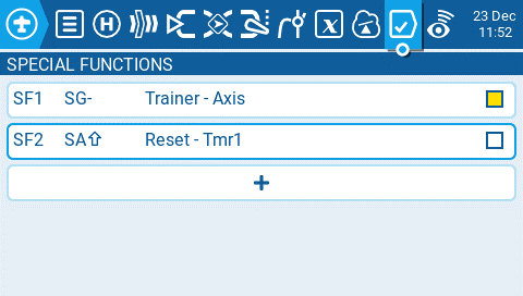
Special Functions
Selecting the + button will allow you to select an unused special function to configure and the special function configuration window will appear. See configuring special functions below for information about configuring new special functions.
Selecting an already configured special function will give you the following options:
- Edit - Opens the special function configuration page
- Copy - Copies the selected special function
- Paste - Pastes a copied special function to the selected special function. Note: this will overwrite the value of the selected special function with the copied special function.
- Insert - Inserts a blank special function above the selected special function
- Clear - Clears all configured options from the selected special function.
- Delete - Deletes the selected special function.
- Enable - Enables special function
- Disable - Disables special function
Configuring Special Functions
All special functions have the configuration options below. Additional options may be added based on the selected function. See the Functions section below for these additional options.
- Trigger- The switch that will make the special function active.
- Function - The function that will be used. See below for function descriptions.
- Enable - Toggle on / off to enable the function. To be able to activate the special function by a switch, it must be enabled. Disabled special functions will not function regardless of the configured switch position.
Functions
Below are all the available functions in EdgeTX, what they do, as well as what other configuration options exist specifically for that function.
Override (Channel Override) - Overrides the defined channel with the defined value.
- CH - Channel to be overridden
- Value - Value to replace the normal channel value. (Range -100 to +100)
Trainer - Enables trainer mode.
- Value - Specifies which controls will be given over to the student. Options include Sticks (all sticks), Rud (Rudder), Ele (Elevator), Thr (Throttle), Ail (Aileron), and Chans (all channels).
Inst. Trim (Instant Trim)- Sets all trims to the current values of their respective sticks.
Reset (Reset Timer)- Resets the timer or telemetry specified in the value back to their initial values.
- Reset - Options are Timer 1, Timer 2, Timer 3, Flight, and Telemetry. See Reset Telemetry for more information on what data is reset for each option.
Set (Set Timer) - Sets the specified timer to the specified value.
- Timer - Options are Timer 1, Timer 2, Timer 3
- Value - The range is 00:00:00 to 08:59:59
Adjust (Adjust Global Variable) - Changes the value of the specified global variable.
- Global var - Select the global variable that you want to adjust.
- Mode - Select the mode to change the global variable. Options are: Constant, Mixer Source, Global var, Inc/Decrement
- Constant - Sets the specified global variable to the defined constant value.
- Mixer Source - Sets the specified global variable to the defined mixer source value.
- Global Var - Sets the specified global variable to the defined global variable value.
- Inc/Decrement - Increments/decrements the specified global variable by the specified amount.
Volume - Changes the radio volume. The change source is specified in the Volume dropdown.
SetFailsafe - Sets the custom failsafe values for the selected module (Internal/External) to the current stick position when activated. For this option to work, the Failsafe mode for the RF module must be set to custom.
Play Sound - Plays the sound selected in the value field when activated.
- Value - Sound to play. Possible values are Beep1/2/3, Warn1/2, Cheep, Ratata, Tick, Siren, Ring, SciFi, Robot, Chirp, Tada, Crickt, AlmClk. Note: SD card sound pack is not required.
- Repeat - Frequency to repeat the sound. Options are !1x (do not play at startup even if the switch is active), 1x (play once), 1s thru 60s (play every xx seconds).
Play Track - Plays the .wav sound file selected in the value field when activated.
- Value - .wav sound file to play from the SD card.
- Repeat - Frequency to repeat the track. Options are !1x (do not play at startup even if the switch is active), 1x (play once), 1s thru 60s (play every xx seconds).
Play Value - Announces the value of the selected element in the value field.
- Value - The source for the value to announce. It can be an input, stick, pot, slider, trim, physical and logical switch, trainer import channel value, global variable, telemetry sensor or channel.
- Repeat - Frequency to repeat the announcement. Options are !1x (do not announce at startup even if the switch is active), 1x (announce once), 1s thru 60s (announce every xx seconds).
Lua Script - Executes the Lua script defined in the value field. The Lua script must be located in /SCRIPTS/FUNCTIONS/ folder on the SD card. Lua scripts that display information on the screen cannot be executed with this special function.
- Value - LUA script file to play from the SD card.
- Repeat - Frequency to repeat the Lua script. Options are: ON (repeat indefinately as long as switch is active) or 1x (once)
BgMusic - Plays the .wav file selected in the value field on a loop when enabled. The file shall be in the SOUNDS/(language)/ folder on the SD card.
BgMusic II - Temporarily pauses the .wav file playback specified in the BgMusic
Vario - Enables the variometer beeping sound for the ascent and descent of the model.
Haptic - Causes the radio to vibrate (haptic feedback) when enabled.
- Value - Type of vibration pattern. Options are: 0 - 4.
- Repeat - Frequency to repeat the vibration pattern. Options are !1x (do not vibrate at startup even if the switch is active), 1x (vibrate once), 1s thru 60s (vibrate every xx seconds).
SD Logs - Creates a log .csv file of the radio and telemetry values in the LOGS folder on the SD Card. The radio will create a new entry into the log file based on the frequency configured in the Interval setting. The value options are 0.1s - 25.5s. Each time the function is activated the radio will create a new log file provided that the function is activated at least as long as the value setting. Note: Logging will not start if SD card has less than 50mb of free space.
Backlight - Adjusts the brightness of the radio screen based on the source defined in the value dropdown. Brightness is limited to the On / Off values configured in the Radio Setup -> Backlight Screen.
Screenshot - Creates screenshot as a .bmp file in the SCREENSHOT folder on the SD Card.
RacingMode - Enables racing mode (low latency) for FrSky Archer RS receivers. Racing mode must also be enabled in External RF Module Settings.
No Touch - Disables the touch interface for touchscreen-enabled radios.
Set Main Screen - Changes the current visible screen to the screen number defined.
- Value - The screen number as defined in the Screens settings.
- Repeat - When the switch remains active, the repeat value determines how often the special function will change the screen to the defined screen. Options are !1x (do not change at startup even if the switch is active), 1x (change once), 1s thru 60s (change every xx seconds). This is useful because when the switch has been activated, the user can still manually switch screens, and then it will change back to the defined screen after the defined duration.
Audio Amp Off - Disables the Audio Amplifier so that no sound comes from the speaker, including annoying feedback or interferance. This option is only available on select radios.
Telemetry
Telemetry is data received from the model to the radio from various sensors. These sensors may be in included in the radio receiver or flight controller, or may be separate sensors, such as GPS, variometer, or magnetometer. Telemetry data that is received can be displayed by EdgeTX in widgets, configured in alarms or audio call-outs.
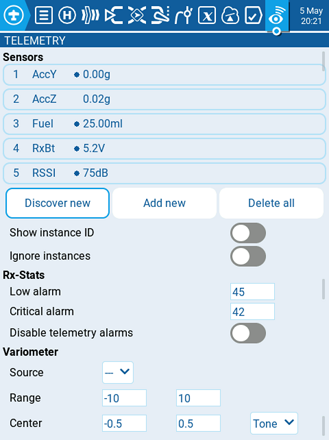
Telemetry screen in Model Settings
Sensors
All prevously configured sensors are listed here. Sensors that are highlighted have received data since the model was loaded or the telemetry values were reset. A small circle icon will flash to the left of the sensor value when it has received a data update. Sensor values in black designate the sensors that are receiving regular updates. Sensor values that are red are no longer receiving regular updates. See Recognized Sensors for a list of commonly used sensors in EdgeTX.
The following options are listed under the sensor list.
- Discover New: When selected, it will look for new sensors on the model and automatically configure them.
- Add New: When selected, it will create a new blank sensor for that must be configured manually.
- Delete All: This option will delete all prevously configured sensors. Note: This button will not be visible if there are no sensors configured.
- Show instance ID:
- Ignore Instances: This options prevents mutltiple sensors from reporting the same telemetry data.
If you select a specific sensor, you will get the following options:
- Edit: Allows you to edit the sensor's configuration options.
- Copy: Creates a copy of that sensor.
- Delete: Deletes that sensor.
See the Sensor Configuration Options page for detailed description of all the configuration options for setting-up or editing sensors.
Rx-Stats
Here you can configure the threshold for the RX alarms. The Rx-Stats label will change (Rx-Stats, RSSI, Rqly, Sgnl) depending on the protocol that is used with the model.
- Low alarm - The threshhold value when the "RF signal low" voice prompt will be played. The recommended value is 45.
- Critical alarm - The threshhold value when the "RF signal critical" voice prompt will be played. The recommended value is 42.
- Disable telemetry alarms - When enabled, no alarm voice prompts will be played.
Variometer
A variometer detects changes in the model altitude. EdgeTX can alert the user of these altitude changes by providing a rising/lower pitched tone. Use the Variometer menu on the Radio Setup page to set the actual frequency and volume of the tone to be played. The following options exist to configure the variometer alarm.
- Source - Specifies the sensor to use as the variometer. It is selected from the telemetry sensors added in Sensors section.
- Range - Specifies the ascent/descent range that will trigger the change in the Variometer beeping pitch. If climb/descent rate is within the range specified here, beeping pitch will change according to that value. When it goes beyond the range specified here, beeping pitch will stop changing. Units are meters/second or feet/second based on the Units setting on the Radio Setup page.
- Center - Specify the range for ignoring changes in climb/descent rates. When the climb/descent rate is within the range specified here, the beeping pitch will not change.
- Tone/Silent - Specifies whether to beep when climb/descent rate is within the range specified by Center.
Sensor Configuration Options
The below options can be configured for sensors:
- Name: Name of the sensor - up to 4 characters.
- Type: Options are custom or calculated. Custom sensors are defined by the hardware. Calculated sensors are a sensors whose value is calculated using other sensors values. See below for more information on calculated sensors.
- ID: This number indicates what type of sensore it is. It contains two parts. The first part is the ID number which defines the sensor type. The second part is the instance number for the hardware. If multiple sensors of the same type are configures, the instance numbers must be unique.
- Unit: The unit for the sensor. This unit is used when the sensor value is displayed on the screen or read aloud.
- Precison: Specifies the number of digits after the decimal point when the sensor value is displayed on the screen. The number is truncated based on this setting.
- Ratio: Specifies the ratio value to multiply with the sensor value as needed by some sensors.
- Offset: Specifies the offset value to add to the sensor value.
- Auto Offset: When selected, the first received value is used as offset. You can use the Reset telemetry option to reset the offset on already configured sensors.
- Positive: When selected, the value of the sensor will be displayed only when it is a positive number. Displays zero when the sensor value becomes a negative number.
- Filter: When selected, the sensor value becomes a rolling average of the last 5 received values.
- Logs: When selected, the value of this sensor will be saved in the log file. SD Card logging is configured in Special Functions or Global Functions.
Calculated sensors contain the additional configuration options:
- Formula: Type of calculation to use. Options include:
- Add: Add the values of up to 4 designated sensors.
- Average: Calculates the average value of up to four designated sensors.
- Minimum: Find the minimum value of up to 4 designated sensors.
- Maximum: Find the maximum value of up to 4 designated sensors.
- Multiply: Multiplies the value of 2 sensors.
- Totalize: Calculate the cumulative value of one sensor.
- Cell: This is the formula for FrSKY Lipo battery sensor. It displays cell voltage specified by the number in "Cell index" field.
If you specify "Lowest" in "Cell index" field, the voltage of the cell with the lowest is displayed.
If you specify "Highest" in "Cell index" field, the voltage of the cell with the highest is displayed.
If you specify "Delta" in "Cell index" field, the voltage difference between lowest and highest cell is displayed - Consumpt: Calculates the power consumption (mAh) by cumulatively add the values of current sensor.
- Distance: Calculates the distance between the receiver and the radio using GPS sensor and altimeter values.
- Source 1, 2, 3, 4: The sensors that will provide the argument values that are used in the formula defined above.
- Persistent: When selected the sensor values will be saved when switching between models or powering down the radio.
Common Telemetry Sensors
The following sensors are commonly used and normal automatically detected by EdgeTX:
| Name | Description | Data source |
|---|---|---|
| 1RSS | Received signal strength antenna 1 (RSSI) | Receiver |
| 2RSS | Received signal strength antenna 2 (RSSI) | Receiver |
| Rqly | Receiver link quality (valid packets) | Receiver |
| RSNR | Receiver signal-to-noise ratio | Receiver |
| RFMD | Receiver packet rate | Receiver |
| TPWR | Transmitter transmitting power | Transmitter |
| TRSS | Transmitter signal strength antenna | Transmitter |
| TQly | Transmitter link quality (valid packets) | Transmitter |
| TSNR | Transmitter signal-to-noise ratio | Transmitter |
| ANT | Sensor for debugging only | Transmitter |
| GPS | GPS Coordinates | GPS / Flight Controller |
| Alt | GPS Altitudes | GPS / Flight Controller |
| Sats | GPS Satellites acquired | GPS / Flight Controller |
| Hdg | Magnetic orientation | GPS / Flight Controller |
| RXBt | Battery voltage | Flight Controller |
| Curr | Current draw | Flight Controller |
| Capa | Current consumption | Flight Controller |
| Ptch | FC Pitch angle | Flight Controller |
| Roll | FC Roll angle | Flight Controller |
| Yaw | FC Yaw angle | Flight Controller |
| FM | Flight mode | Flight Controller |
| VSPD | Vertical Speed | Flight Controller w/ Baro |
Radio Settings
The Radio Settings section contains all the options to configure your radio. Across the top of the page you will see icons that will take you to different pages of radio settings when selected. The default screen for the radio settings is the Tools screen.
Icons at the top of the radio settings screen include (in order from left to right):
Tools
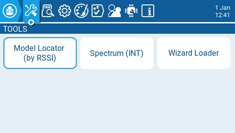
Tools Screen
The Tools page in Radio Settings is where you can select Lua script-based tools for execution. Lua scripts that are located on the SD card in the Tools folder will be listed here. Selecting a tool will execute it in full-screen mode. By default, EdgeTX includes several tools. Other tools can be downloaded and added to the SD card as well. The following tools are included in the default EdgeTX SD card.
Model Locator (by RSSI)
Model Locator tool
The Model Locator tool helps to find a lost model based on the RSSI (if still available). The widget produces an audio representation (variometer style) of the RSSI from the lost model. The widget will also display the RSSI in a visible colorized bar (0-100%).
Spectrum (INT)
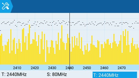
Spectrum Analyzer (INT) tool
The Spectrum Analyzer tool will show the strength of signals in the 2.4GHz band. It uses the internal MULTI-Module as a 2.4GHz spectrum analyzer.
The display shows frequencies on the 2.4GHz spectrum, from 2400MHz to 2480MHz. The X (horizontal) axis shows the frequency in MHz and the Y (vertical) axis shows relative signal strength.
T: Frequency at the center of the plot (fixed at 2440MHz)
S: Bandwidth of the plot (fixed at 80MHz)
T: Position of the cursor (vertical line)
Pressing ENT and scrolling left and right allows the T value to be changed, which will move the vertical line to highlight a specific frequency.
Wizard Loader
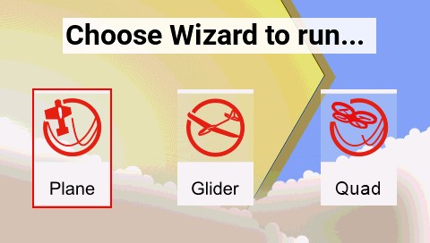
Wizard Loader tool

Plane Wizard
The Wizard Loader tool assists you in setting up a new model by running a setup wizard for a particular model type. Once the model type is selected, the wizard will take you through a series of prompts and then configure your selected model based on the information provided.
NOTE: The wizard does not create a new model, it only configures the currently selected model. You must manually create a new model first and then run the wizard. If you run this wizard on an already configured model, it will overwrite your model settings!
SD Card
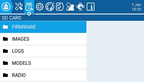
SD Card screen
The SD Card screen shows you the contents of your SD card, allows you to navigate the folders and interact with the files in the folders. All folders contain a README.txt file that describes what type of files belong in this folder. After selecting a file in one of the folders, you will be presented with some of the options below, depending on the file type that was selected:
- Assign bitmap - Assigns the selected image file as the model image of the currently selected model.
- Copy - Copies the selected file.
- Delete - Deletes the selected file.
- Execute - Executes a Lua script. Used for files ending in .lua
- Flash [target]- Flashes the selected firmware file to the select target module. Examples: Flash Bootloader, Flast Internal Multi.
- Paste - Pastes the copied file.
- Play - Plays the selected sound file.
- Rename - Renames the file.
- View text - Views the selected .txt, .csv, and .lua files.
The folders listed on the SD card screen are the same as what you will see when connecting your radio to your computer. Below are the folder names and explanations for all the folders that come with the default EdgeTX SD Card.
FIRMWARE
Place the firmware files that you want to flash in this folder. This folder is empty by default (except for the readme.txt file). When selecting a .bin file you will be given the option to flash the firmware to a particular module. Also, only firmware files in this location will be visible from the bootloader menu. Selecting a .frsk file will give you the option to "Flash RX by int OTA".
IMAGES
Place your custom model or splash screen image files in this folder. This folder is empty by default (except for the readme.txt file). Selecting an image file will give you the option to Assign Bitmap, which assigns the selected image file as the model image of the currently selected model.
The ideal image size for model images used for thumbnails on the Model Manager screen is 156x92 pixels. If you plan to use the Model Info widget, you may want a increase the image size to 192x114 pixels for better visual quality at the increased size. For performance reasons, it is NOT recommeded to use a higher resolution image. The picture format should be .png. The image file name should not exceed 9 characters.
The ideal image size for Splash Screen images is the actual radio screen size (480x272 pixels for most color screen radios). The picture format should be .png. The image file name must be splash.png. Screen dimensions for the supported color screen radios can be found here.
Users can configure a custom image to be displayed during the radio shutdown by adding a custom shutdown.png to the IMAGES folder.
LOGS
This is where the log files that are configured in the special function SD Logs are written. These files can be viewed with the View text option. This folder is empty by default (except for the readme.txt file).
MODELS
This is where the model files, label information, and preflight checklists are stored. Each model will have a model[#].yml file that contains all configured options. Additionally, there is a labels.yml file that contains all the label information for your models.
Models that are deleted via the radio will be moved to the DELETED folder that is included in this folder. The remaining model files are what will be visible on the Model Select screen.
Any model files that are found in this folder that are not listed in the Models.yml file (if used) will be moved to the UNUSED folder.
If you have configured the Display checklist option in model settings, the model notes file goes in this folder. The model notes file must be a .txt file and must have the EXACT same name as the model it is for, for example: Mobula6.txt. The text in the file is up to the user.
RADIO
This folder contains the radio.yml file. This file contains all the radio configuration data. If this file is corrupted or missing, the radio will go into Emergency Mode and will create a new radio.yml file with the default settings.
SCREENSHOTS
This is where the screenshot image files that are configured in the special function Screenshot are written. This folder is empty by default (except for the readme.txt file).
SCRIPTS
This folder and its subfolders are where the Lua scripts get placed. It contains the following sub-folders by default. You can download additional Lua scripts from https://github.com/EdgeTX/lua-scripts.
- Functions - This folder is where the functions Lua scripts that can be activated by the special function Lua Script must be placed. This folder is empty by default (except for the readme.txt file). More information about function Lua scripts can be found here: Function Scripts.
- Mixes - This folder is where the Lua mixer scripts shall be placed. This folder is empty by default (except for the readme.txt file). More information about Mixer Lua scripts can be found here: Custom Mixer Scripts
- Tools - Contains the Lua scripts that are available in the Tools screen.
- Wizards - Contains the Wizard Lua scripts that are available in the Tools screen.
SOUNDS
This folder is where the EdgeTX sound packs for your radio get placed. The sound packs are language-specific and correlate to the Voice language option in Radio Setup. Selecting a sound file from this folder will give you the option Play, which plays the selected sound file.
Sound packs are available for manual download at: https://github.com/EdgeTX/edgetx-sdcard-sounds/releases. It is also possible to create custom sounds to use in EdgeTX. For your custom sounds to be playable by EdgeTX ensure that they meet the following criteria:
- File Name: 123456.wav (up to 6 characters plus .wav)
- Sample Rate: 32 kHz (or 16 Khz, 8Khz)
- Bits / Sample: 16 (or 8)
- Tracks: 1, mono
- Compression Codec: PCM
TEMPLATES
This is where model template files are stored. By default, it will have the following sub-folders:
- PERSONAL - If you save your models as templates, then they get stored here.
- SoarETX - A collection of sailplane templates by: Jesper Frickmann
- Wizard - Simple model templates that use the Lua Wizard scripts to configure the models.
THEMES
This folder contains the theme packs for EdgeTX. The EdgeTX SD card comes with several theme packs automatically installed.
EdgeTX Installed theme packs
You can download and add additional themes from: https://github.com/EdgeTX/themes.
WIDGETS
This is where the widget files are stored. You can add additional widgets to this folder to use with EdgeTX. For more information about the widgets that are pre-installed with EdgeTX, see Widgets. You can download additional widgets from https://github.com/EdgeTX/lua-scripts.
Radio Setup

Radio Setup Screen
The Radio Setup screen is where you configure basic settings for your radio. It contains the following options:
Date - The current date. This date is used for the SD card log files.
Time - The current time. This time is used for the SD card log files.
Additional Settings Buttons - Additional configuration options for the named areas are available when selecting these buttons. More information about these configuration settings is on the next page - Additional Radio Settings
Splash Screen - Duration that the splash screen will be displayed.
Startup Sound - Toggles whether to enable/disable startup sound.
Pwr Off delay - The delay between when the power button is pushed and when the radio shuts off. The options are: 0s, 1s, 2s, 3s, 4s. It is recommended to set at least a 1s delay in order to prevent the radio from being shut off in the case of an accidental button press.
Owner ID - Custom registration ID used only for users with ISRM modules.
Country code - Used by some RF modules to ensure adherence to local regulatory RF requirements. Options are America, Japan, Europe.
Voice language - Language for the voice pack. This setting and the voice pack folder on the SD card must match for the sounds to be played.
Units - Units of measure. Options are metric or imperial.
PPM Units - Level of accuracy for PPM values are displyed. Options are 0.- or 0.0
Play delay (sw. mid pos) - The minimum time in milliseconds a switch must be in the middle position before a special function will get activated. This is used to prevent the middle position from being activated on a three-position switch when switching from low position to high position.
USB Mode - Sets the default action when a USB cable is plugged into the USB data port and the radio is powered on. Options are: Ask, Joystick, Storage, and Serial.
Hats Mode: how the hat switches will function (NV14 & EL18 only).
- Trims only: The Trim hat switches will be used to adjust the trim values only.
- Keys only: The Trim hat switches will be used to navigate the menu options (as described below)
- Switchable: Trim hat switch functionality can be changed between Trims and Keys on-the-fly.
Rotary Encoder Mode - Set to Normal by default. The Inverted option reverses the direction of the roller.
Default Channel Order - The default channel order for new models and the trainer screen. The letters stand for: A = Aileron (Roll), E = Elevator (Pitch), T = Throttle, R = Rudder (Yaw). Changing this setting does not affect existing models.
Mode - The stick mode that will be used for the transmitter. Defined by what actions the left stick takes. The options are:
| Option | Left stick H | Left stick V | Right stick H | Right stick V |
|---|---|---|---|---|
| 1: Left = Rud+Ele | Rudder (Yaw) | Elevator (Pitch) | Aileron (Roll) | Throttle |
| 2: Left = Rud+Thr | Rudder (Yaw) | Throttle | Aileron (Roll) | Elevator (Pitch) |
| 3: Left = Ail+Ele | Aileron (Roll) | Elevator (Pitch) | Rudder (Yaw) | Throttle |
| 4: Left = Ail+Thr | Aileron (Roll) | Throttle | Rudder (Yaw) | Elevator (Pitch) |
Additional Radio settings
Selecting one of the 6 buttons on the Radio Setup screen will take you to one of the additional setting screens below.
Many of the additional settings here are self-explanatory. Only those settings needing clarification will be mentioned below.
Sound

Sound Options
Mode - configures when to play sounds.
- All - Beeps when the buttons are pressed and sounds are played when there are alerts or warnings.
- No Key - No beeps when buttons are pressed or the scroll wheel is turned but does play sounds when there are alerts or warnings. Also plays sounds triggered by special functions.
- Alarm - Only plays alarm or warning sounds. Also plays sounds triggered by special functions.
- Quiet - No Beeps or sounds are played.
Volume
The master volume for the radio.
Wav volume
The volume for alerts and warnings and sounds that are played with the Play track special function
Background volume
The volume for background .wav files (music) that are played with the BGMusic special function
Variometer
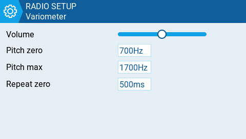
Variometer options
Repeat Zero
The time before the tone repeats in milliseconds.
Haptic
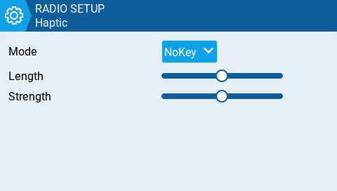
Haptic (vibration) options
Mode - configures when the radio vibrates.
- All - Vibrates when the buttons are pressed and when there are alerts or warnings.
- No Key - No vibrations when buttons are the pressed or scroll wheel is turned but does vibrate when there are alerts or warnings.
- Alarm - Only vibrates for alarms or warning sounds.
- Quiet - No vibrations are made.
Alarms
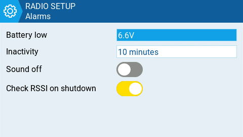
Alarm options
Sound Off
An "alarms disabled" visual warning is displayed when the transmitter is turned on if the sound mode is set to quiet.
Check RSSI on Shutdown
Checks if a receiver is still connected to the radio on attempted shutdown. Makes a audio and visual alert if one is detected.
Backlight
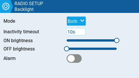
Backlight options
Mode
- Off – Always off.
- Keys – Turns on when buttons are pressed.
- Ctrl – Turns on when sticks, switches, and knobs are used.
- Both – Turns on when buttons, sticks, switches, and knobs are used.
- ON – Always on.
Time
The length in seconds that the backlight is on. The minimum value is 5 seconds. The maximum value is 600 seconds.
Alarm
The backlight turns on when there are alarms or warnings.
GPS

GPS options
Time Zone:
The time offset from UTC where the radio is being used. Can be configured in 15 minute increments.
Adjust RTC
Adjust the transmitter's real-time clock to match the time determined by the GPS.
Coordinate Format
The GPS coordinate format that will be displayed.
Enabled Features

Enabled Reatures
The Enabled Features section of Radio Setup allows you to configure the Global settings for which tabs are visible in the Radio Setup and Model Settings area of EdgeTX. The configuration setting for the active model will show to the right of the toggle switch. The model configuration will override the global configuration.
EXCEPTION: Turning off the Global / Special Functions tab will disable configured global / special functions for that model.
Manage Models
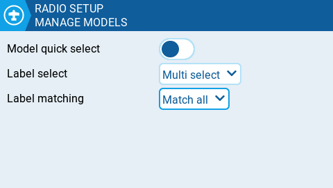
Manage Models settings
Model quick select - Affects Manage Model screen. Both options require you first to select the desired model using the scroll wheel or short tap.
- When OFF: short/long tap (short/long ENTER) on the selected model will show the menu, where you can "Select model" to set it to active.
- When ON: short tap (short ENTER) on the selected model will set it active immediately. To activate the menu, make a long tap or long ENTER.
Label select - 'Multi select' or 'Single select' (Multi select is the default). If Single select is chosen then only a single label can be selected.
Label matching - 'Match all' or 'Match any' (Match all is the default). Match all is the current logic - only models having all selected labels are shown. Match any will show models with any of the selected labels.
Favorites matching - Only available when 'Match any' is selected for Label matching. Options are 'Must match' and 'Optional match' (Must match is the default). Only applies when 'Favorites' is in one of the selected labels. If 'Must match' is selected then only shows models that have Favorites AND the other selections. If 'Optional match' is selected then models that match Favorites OR any of the other labels are shown.
Themes
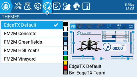
Themes Screen
The Theme screen allows you to apply different colored themes to your radio. By default, the EdgeTX SD card comes with the themes shown above. Long pressing on a selected theme will give you the following options:
- Set Active - Sets the selected theme as the active theme.
- Edit - Opens the theme editor to edit the selected theme.
- Duplicate - Makes a copy of the selected theme.
- Delete - Deletes the selected theme.
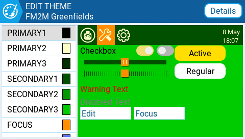
Edit Theme Screen
Selecting the Details button will open the Edit Theme Details screen. Here you can edit the name, author and description of the them.
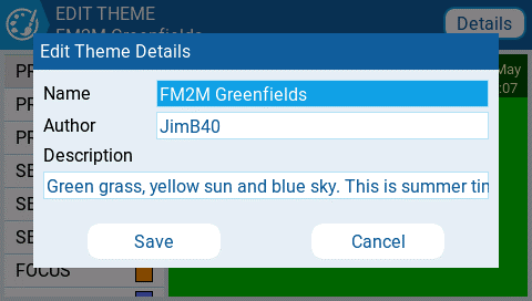
Edit Theme Details Screen
To edit a theme in the Theme Editor, select the color variable from the list on the left side of the screen. Once you do, the Edit Color screen will be shown.
.jpg)
Edit Color Screen
Select the color using either the color scales on the left side of the screen. You can choose between the RGB and HSV color scales with the buttons at the upper right side of the screen.
Once you have your desired color, press the theme logo in the upper left corner to go back to the Edit Theme screen to select another color variable to edit. Once you are finished, press the theme logo to exit the Theme Editor and save your changes.
Global Functions
Global functions are special functions that apply to all models on the Radio. They are configured exactly as model Special Functions and the same functions are available. For more information about configuring Global Functions, refer to the Special Functions section as they are essentially the same.
Trainer
The Trainer screen in Radio Settings is used to configure how the radio in Master mode will handle the signals from the radio in Slave mode.
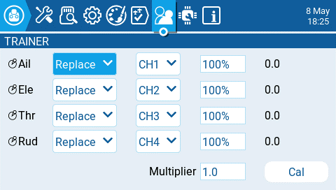
Trainer Screen
For each of the four main control inputs (Ail, Ele, Thr, Rud), the following options can be configured (for each row, from left to right).
- Mode - How the radio in Master mode will handle the signals from the radio in Slave mode.
- OFF - Stick values from the radio in Master mode will be used - no input from the radio in Slave mode.
- Add - Adds the stick values from both the radios in Master and Slave modes.
- Replace - Replaces the stick values from the radio in Master mode with the stick values from the radio in Slave mode. (Default)
- Source channel - The channel from the radio in Slave mode that is mapped the control input.
- Weight - Percentage of stick travel to use of the radio in Slave mode. Use negative values to change the stick direction.
- Cal (calibrate)- Sets the center stick value of the radio in Slave mode.
- Multiplier - This value changes the weight of all the sticks together.
Hardware
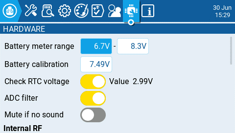
Hardware Screen
The Hardware screen is where you configure hardware specific-settings for your radio. It contains the following configuration options:
Battery meter range - Sets the maximum and minimum voltage for the battery meter. This should be set based on the type of battery you are using.
Battery Calibration - Set this value to match the transmitter battery voltage.
Check RTC voltage - When enabled, checks the RTC battery at startup and warns you if the battery voltage is low.
ADC Filter - Enables or disables the ADC Filter. This filter can also be enabled/disabled per model in the model settings.
Mute if no sound: - When enabled, puts the transmitter in mute mode until a sound needs to be played. This prevents interference noise from high-powered TX modules from coming out of the transmitter speakers.
Internal RF Type
Select the module type for the internal module bay. Options are: Multi, XJT, ISRM, CRSF. When CRSF is selected, you can also select the baud rate. You can read more about baud rates here.
External RF Sample Mode
Options are Normal and OneBit. The default setting of Normal should be used by most users. Only users of X9D+ and X7 radios may want to use OneBit mode.
Bluetooth
Mode - mode that the bluetooth module will be used in. The options are:
- --- - Off
- Telemetry - used for sending telemtry data over bluetooth.
- Trainer - used for bluetooth trainer mode
Name - the name the bluetooth device will be seen as.
Settings Cog Icon - when selected will show you:
- PIN Code - PIN code for bluetooth device in the radio (visible in Telemetry mode only)
- Local addr - Identifying address of the bluetooth device in the radio.
- Dist addr - Identifying address of bluetooth device that radio is connected to.
Serial Port
Displays a list of available auxiliary serial ports that can be configured and used. The listed ports are based on the ports that are available in the particular radio hardware. The ports listed below are for example only and may not be present in your radio.
- AUX1 - First available auxiliary serial port can be configured with the below options:
-
OFF - Turned off.
-
Telem Mirror - The same telemetry data that goes to the external module bay is sent to the serial port.
-
Telemetry In - Receive telemetry data over the serial port.
-
SBUS Trainer - Connect the Instructor and Student radios over the serial port.
-
LUA - Send/receive data to/from Lua script.
-
GPS - Receive GPS telemetry data over the serial port.
-
CLI - Send commands to the radio via the command line.
-
External Module - This allows configuring the external access mod on runtime rather than by compilation option. First, configure the hardware port (only available on
AUX1asAUX2has no TX DMA)

Then the module can be chosen:

-
AUX2 - Second available auxiliary serial port (depending on hardware), which has the same options as AUX1, except for External Module
-
USB-VCP - Virtual COM Port. This is one of the options presented when connecting your radio to the PC with most radios. Is often set to 'CLI' for radios with internal ExpressLRS RF modules in order to do firmware updates.
-
- Port Power - Enables or disables the power output on the power supply pins next to serial ports that are available on some radios (presently only TX16S has this feature).
Inputs
Calibration - For calibrating your physical radio controls (sticks, pots, sliders & 6-position switch). The radio will prompt you through the calibration steps.
Axis, Pots, and Switches Buttons
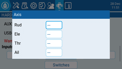
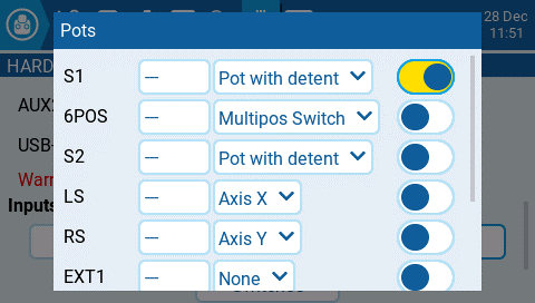
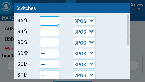
Selecting one of the Axis, Pots, or Switches buttons will open the configuration screen. On these screens, you will see all the physical radio controls pre-defined by EdgeTX. Here you can add a 3 character label to the control as well as change the type of control as needed. Addionally, controls listed under the Pots screen can also be configured to be inverted.
Debug
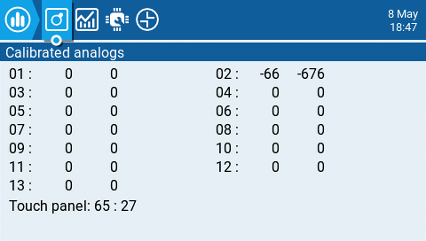
Analog Debug Screen
.jpg)
Switches Test Screen
The debug section allows for testing and debugging of the analog controls and keys.
Analogs - These screens will show you the data for your analog controls (Sticks, Sliders, Pots, 6-position switch) and the touch screen on your radio. There are four views - Calibrated analog, Filtered Raw Analog with deviation, Unfiltered raw analog, and Min Max and range.
Keys - This screen will show you the digital data for your keys, switches, trims, and the rotary encoder (roller).
Version
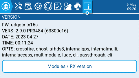
Version screen
The Version screen displays information about the current EdgeTX version that is being used:
- FW - Firmware name
- VERS - Firmware version
- DATE - Date firmware was compiled
- TIME - Time firmware was compiled
- OPTS - Build options that were enabled when compiled.
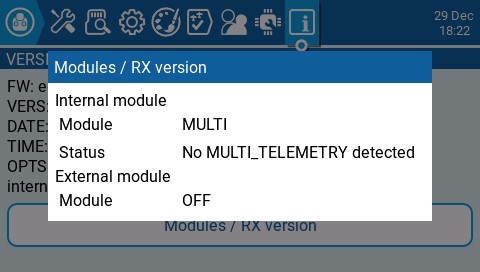
Modules / RX Version screen
The Modules / RX Version gives you information about the activated RX modules for the currently selected model.
Screen Settings
The Screen settings section of EdgeTX is where you can customize your main views and add additional views (up to 10 in total). When selecting Screen Settings from the main navigation menu it will open Main view 1. If other main views have been added, you may select them from the number tab at the top of the screen to adjust their settings. All main view tabs have the following configuration options and are configured individually:
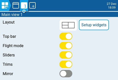
Main view 1 screen
- Layout - Selects the screen layout for the widgets. It is possible to divide the screen in up to two columns and up to 4 rows, with a widget in each cell.
- Setup Widgets - see Setting up widgets below.
- Top bar - Toggles whether the top widget bar will be visible on the selected main view.
- Flight mode - Toggles whether the flight mode name (if configured) will be visible on the selected main view.
- Sliders - Toggles whether the slider bars will be visible on the selected main view.
- Trims - Toggles whether the trim bars will be visible on the selected main view.
- Mirror - Toggles whether to mirror the selected widget layout.
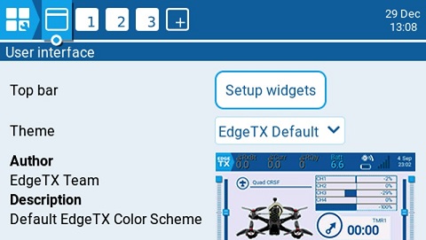
User Interface screen
Selecting the user Interface button to the left of the Main view 1 tab will open the user interface configuration screen. It contains the following options:
- Top bar Setup Widgets button - Sets up the widgets that will be displayed on the top bar. See Setting up widgets below for information on how to setup widgets.
- Theme - Applies the selected theme to EdgeTX. A preview of the theme is below the dropdown. EdgeTX comes with several themes installed. Additional themes to download as well as instructions for creating your own themes can be found here: https://github.com/EdgeTX/themes

Top Bar Widget Setup
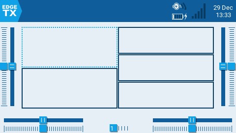
Main View Widget Setup
Setting up widgets
Selecting the setup widgets button will display the main view or top bar with the widget cells outlined in a hashed line. You can assign a widget to a cell by selecting the cell and then the widget you want to assign to it from the drop-down menu. After selecting the widget, it will then open the configuration options for the widget for further configuration. Widget descriptions and configuration options for widgets included with EdgeTX are below.
Widgets
Below are descriptions and configuration options for widgets included with EdgeTX.
BattAnalog
BattAnalog Widget
Displays a graphical representation of the charge level of a Lipo/Li-ion. It will automatically detect the cell count of the battery. It works with telemetry where only the total battery voltage is received. The configurable options are:
- Sensor - Sensor for the battery voltage to use.
- Color - Opens the color picker to choose the color for the text.
- Show_Total_Voltage - Shows total battery voltage (instead of calculated cell voltage) when enabled.
- Lithium_Ion - Adjusts the minumum battery voltage used in calculating the remaining battery percentage from 3.0 to 2.8 when enabled.
BattCheck
BattCheck Widget
Displays a graphical representation of the charge level of a Lipo/Li-ion. It works with telemetry where individual cell voltage is received, such as FLVSS liPo Voltage Sensor. The configurable options are:
- Sensor - Sensor for the battery voltage to use.
- Color - Opens the color picker to choose the color for the text.
- Shadow - When enabled, adds a shadow to the text.
- LowestCell - When enabled, shows only the voltage of the lowest cell (vs. showing all cell voltages).
- Lithium_Ion - Adjusts the minimum battery voltage used in calculating the remaining battery percentage from 3.0 to 2.8 when enabled.
Counter
Counter Widget
A counter that incrementally counts. The configurable options are:
- Color - Opens the color picker to choose the color for the text.
- Shadow - When enabled, adds a shadow to the text.
Event Demo
Counter and Event Demo Widgets
Event Demo Widget Full Screen
Demonstrates handling of key and touch events in full screen mode. For demo purposed only. The configurable options are:
- Size - Changes the size of the box in full screen mode.
Flights
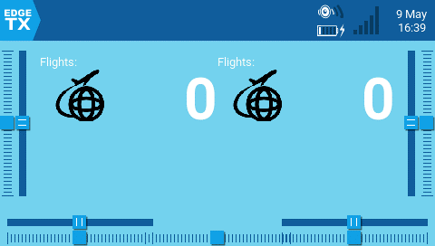
Flights Widget
Counts your number of flights. It will give you a verbal queue when the flight has started, finished as well as the total flights for the model.
The configurable options are:
- switch - Designated Arm/Safe switch.
- motor_channel - Channel for the motor.
- min_flight_duration - Minimum flight duration for the flight to be counted.
- text_color - Opens the color picker to choose the color for the text.
- debug - When enabled, shows status information on the widget.
Additional notes regarding this widget:
The flight is considered successful if after 30sec the engine is above 25%, telemetry is active (to indicated that the model connected), and safe switch ON. The flight is considered ended after 8 seconds of battery disconnection (detected by no telemetry) -- warning: do NOT use this widget if model is using GV9 (GV9 FM0 is where the flight count is stored)!
The widget assumes the following: the model has a motor, the motor is activated on channel 3 (can be configured in settings), there is telemetry with one of the above [RSSI|RxBt|A1|A2|1RSS|2RSS|RQly], there is a safe switch (arm switch), and global variable GV9 is free (i.e. not used).
Gauge
.png)
Gauge Widget
Shows a bar graph for the source value. The configurable options are:
- Source - Source for the gauge.
- Min - Minimum value for the gauge. This value will be 0%
- Max - Maximum value for the gauge. This value will be 100%
- Color - Opens the color picker to choose the color for the gauge text and bar.
Gauge Rotary
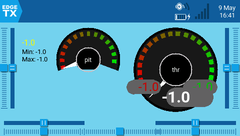
Gauge Rotary Widget
A configurable analog style gauge with a needle. Also shows the minimum and maximum values that were read by the gauge with green and red needles. The configurable options are:
- Source - Source for the gauge.
- Min - The minimum (lowest) gauge value.
- Max - The maximum (highest) gauge value.
- HighasGreen - Enable for a sensor where high values are good. Disable for sensor where low values are good.
- Precision - The precision of the number value to display in decimals.
Ghost
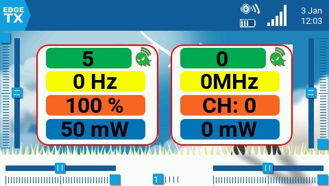
Ghost Widget Normal Mode and VTX Mode
The Ghost widget will display RF receiver or video transmitter telemetry data based on the mode that is configured.
In normal mode, the widget provides RF Mode (RFMD), Frame Rate (FRATE), Link Quality (RQLY), and Transmit Power (TPWR)
In video mode, the widget provides Video Band (VBAN), Video Frequency (VFRQ), Video channel (VCHAN), and Video Power (VPWR)
LibGUI Demo
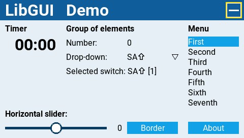
LibGUI Demo Widget
This widget is a demo for the LibGUI library. This library is not normally run by itself. Instead, it provides interactive functions to other Lua scripts that use it. The widget must be run in full-screen mode to demo the library's functionality.
Model info
.png)
Model Info Widget
Displays the selected model name and picture (if configured in model settings). The configurable options are:
- Color - Opens the color picker to choose the color for the name text.
- Size - Size for the name text. Options are STD (Default), BOLD, XXS, XS, L, XL, XXL
- Fill background? - Adds a solid background color to the widget when enabled
- BG Color - Opens the color picker to choose the color for the background.
- Use Theme Color - When enabled, overrides the text color with the text color of the configured theme.
Outputs
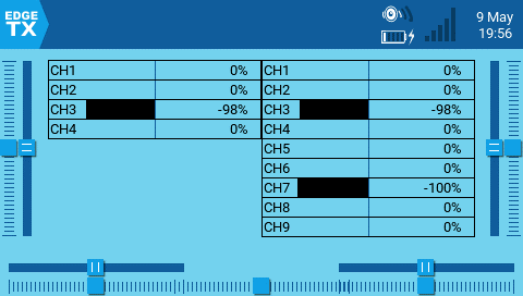
Outputs Widget
Shows the channel output values in a bar graph. The number of channels that are displayed is dependent on the size of the widget. The configurable options are:
- First channel - selects the first channel to display in the widget.
- Fill background - Adds a solid background color to the widget when enabled
- BG Color - Opens the color picker to choose the color for the background.
- Text Color - Opens the color picker to choose the color for the text.
- Color - Opens the color picker to choose the color for the output bars.
Serial Power Port Demo
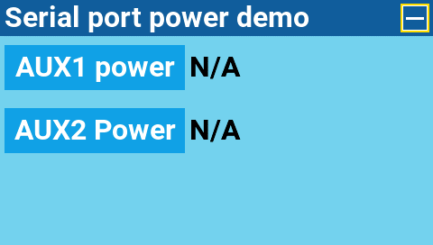
Serial Power Port Demo Widget
A demo widget to show you how the power port can be used. It must be run in full screen mode.
SOARETX
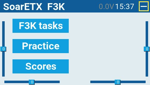
SoarETX Widget
The EdgeTX version of the SoarOTX tool. It is a package of sailplane models for EdgeTX transmitters. It provides Lua scripts for timing and scorekeeping, graphing of log data (e.g. altitude graphs), and model configuration.
For more information about the configuration and use of this widget please see https://github.com/jfrickmann/SoarOTX/wiki/SoarETX-for-color-radios.
A demo of this tool can be seen here: https://www.youtube.com/watch?v=5NSvxUNKM_c
Text
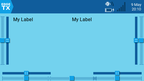
Text Widget
Displays a user-customizable text field. The configurable options are:
- Text - Text to display
- Color - Opens the color picker to choose the color for the text.
- Size - Size for the text. Options are STD (Default), BOLD, XXS, XS, L, XL, XXL
- Shadow - When enabled, adds a shadow to the text.
- Alignment - Alignment of the text in the text box. Options are: Left, Center, Right
Timer
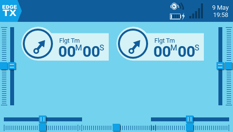
Timer Widget
Displays the selected timer. No configurable options other than timer selection.
Timer2
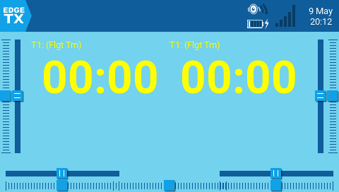
Timer2 Widget
Displays the selected timer with the timer text scaled based on the select widget size and has the following configuration options:
- TextColor - Opens the color picker to choose the color for the text.
- Timer - Timer to display.
- use_days - Shows days when the time value is over 24 hours when enabled.
TxGPStest
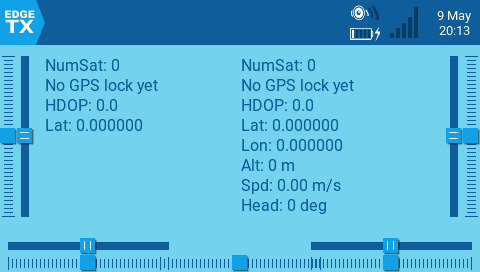
TxGPSTest Widget
Displays GPS Information in text format. There are no configurable options.
Value
Value Widget
Displays a numeric value of the defined source as text. The configurable options are:
- Source - source for the text to be displayed
- Color - Opens the color picker to choose the color for the text. User can choose between RGB and HSV color model to choose the color. You can also select one of the configured theme system colors.
- Shadow - When enabled, adds a shadow to the text.
- Align Label - Aligns the label text. Options include: Left, Center, Right
- Align Value - Aligns the value text. Options include: Left, Center, Right
Value2
Value2 Widget
Displays a numeric value of the defined telemetry source as text. The text will scale based on the size of the widget grid that is selected. The widget will detect the end of the flight (by no longer receiving telemtry) and will then display the min and max values of the configured telemetry sensor.
The configurable options are:
- Source - Telemetry source for the text to be displayed
- Color - Opens the color picker to choose the color for the text. User can choose between RGB and HSV color model to choose the color. You can also select one of the configured theme system colors.
- PostFix - Appends a text label after the configured telemetry name label.
Channel Monitor
The Channel Monitor shows both the output value (top bar) and mix value (bottom bar) for each of the 32 radio channels, spread across 4 pages of 8.
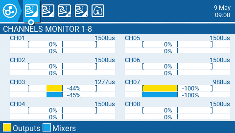
Channels Monitor
The 5th page of the channel monitor is the logical switches monitor. On this page, you will see the status (activated/non-activated) of all logical switches. Logical switches that are activated are highlighted.
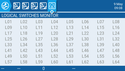
Logical Switches Monitor
Reset Telemetry
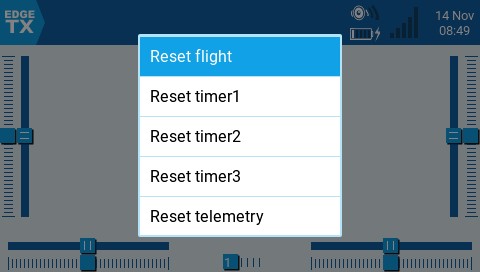
Reset telemetry screen
Reset flight - When selected, this option:
- Resets all timers configured with a persistence setting of Flight to zero.
- Resets all discovered telemetry sensor values.
- Resets all logical switch states
- Triggers the same checks as loading the model - i.e. throttle position, switch state, is failsafe set check, display pre-flight checklist if configured, stuck keys test, etc.
Reset timer 1 / 2 / 3 - Resets only the selected timer to zero regardles of the configured persistence setting.
Reset telemetry - This option resets all discovered telemetry sensor values.
Statistics
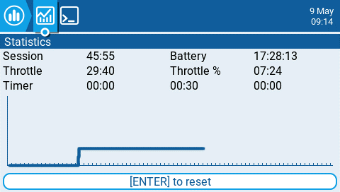
Statistics screen
The Statistics screen presents you with statistics regarding radio usage. Except for Battery, all data is reset once the radio is powered off. The following information is provided:
- Session - The amount of time that the radio has been turned on.
- Battery - The amount of time that the radio has been on since the last reset.
- Throttle - The amount of time that the throttle has was above the 0% stick position.
- Throttle % - The amount of time that the throttle has was above the 50% stick position.
- Timer - The current values of Timer 1, Timer 2, Timer 3.
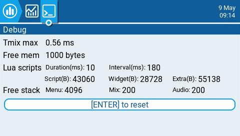
Debug Screen
The debug screen provides data points used by the developers when debugging issues in the software. Most users will not find the information useful on this screen unless debugging issues with developers. The following debug information is provided.
- TMix max - Maximum mixer task duration.
- Free mem - Current free radio memory in bytes.
- Lua scripts
- Duration(ms) - Maximum Lua duration in milliseconds.
- Interval(ms) - Maximum Lua interval in milliseconds.
- Script(B) - Memory used by LUA scripts.
- Widget(B) - Memory used by LUA widgets.
- Extra(B) - Memory used by LUA bitmap functions.
- Free stack
- [Menu] - Minimum free stack memory for menu tasks.
- [Mix] - Minimum free stack memory for mixer tasks.
- [Audio] - Minimum free stack memory for audio tasks.
Аппаратура управления с чёрно-белым (монохромным) дисплеем
.png)
Монохромные аппаратуры, поддерживаемые EdgeTX
EdgeTX поддерживает следующие модели пультов управления с чёрно-белым экраном:
- BETAFPV LiteRadio 3 Pro
- FrSky QX7 / QX7S / QX7 ACCESS / QX7S ACCESS
- FrSky X9 Lite / X9 Lite S
- FrSky X-Lite / X-Lite S / X-Lite Pro
- FrSky X9D / X9D+ / X9D+ SE
- FrSky X9D+ 2019 / X9D+ SE 2019
- Frsky X9E / Frsky X9E Hall
- iFlight Commando8
- Jumper T12 / T12 Plus / T12 Pro Hall
- Jumper T-Lite
- Jumper T-Pro / T-Prov V2
- Jumper T-14
- Jumper T-20
- RadioMaster MT12
- RadioMaster T8 / T8 Pro
- RadioMaster TX12 / TX12 Mark II
- RadioMaster Boxer
- RadioMaster Pocket
- RadioMaster Zorro
Интерфейс пользователя
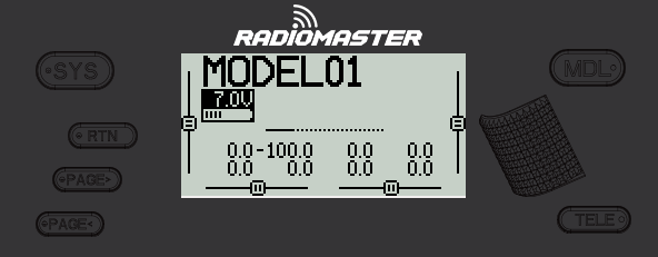
Общеиспользуемые кнопки навигации
Ниже описаны физические кнопки и действия, использующиеся на большинстве пультов управления для навигации в EdgeTX. Если на вашей аппаратуре управления нет таких кнопок, обратитесь к документации производителей (англ.) чтобы ознакомиться с элементами управления вашего устройства.
Кнопки:
- [SYS] - Системные настройки
- Нажмите кнопку [SYS] находясь на главном экране, чтобы перейти на страницу Инструменты (Tools) меню Настроек Аппаратуры (Radio Settings). - [MDL] - Модель
- Нажмите кнопку [MDL] находясь на главном экране, чтобы перейти на страницу Выбора модели (Model Select) меню настроек Модели - [RTN] - Возврат / Назад
- Нажмите кнопку [RTN] для возврата на предыдущую страницу, в предыдущее меню или отмены действия - [PAGE>] / [PAGE<] - Следующая / Предыдущая страница
- Используется для навигации между различными экранами, вкладками или вариантами настройки, в зависимости от текущего экрана. - [TELE] - Телеметрия
- Нажмите кнопку [TELE] чтобы перейти к настроенным экранам телеметрии. Больше информации о экранах телеметрии доступно в разделе Дисплей (Display) . - [Ролик] или [Поворотный энкодер]1 - Следующее и предыдущее значение
Ролик используется для навигации по параметрам меню. - [Enter] - Ввод
- Используется для выбора варианта, запуска функций и ввода значений
- Нажмите на [Ролик] или [Поворотный энкодер] как на кнопку, чтобы выбрать или ввести значение.
На разных моделях пультов управления используются разные типы поворотных переключателей (энкодеров). Ролик (Roller), он же барабан или колесо прокрутки - обычно полуутоплен в корпус, его удобно крутить большим пальцем. Поворотный энкодер (Dial), он же "крутилка" или ручка - выступает из корпуса и лучше подходит для вращения двумя пальцами. На современных моделях оба типа энкодера обычно имеют возможность нажать их как кнопку.
Главный Вид (Main View)
Главный Вид - это основной раздел пользовательского интерфейса, по умолчанию отображаемый на дисплее аппаратуры. В этом виде представлена такая информация как: имя модели, положение триммеров1, напряжение батареи питания аппаратуры, режим полёта, уровень сигнала на приёмнике и таймеры. В нижней части экрана также отображается системное время на всех экранах главного вида. В EdgeTX 5 экранов главного вида.
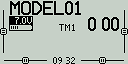
Экран 1 - Таймеры
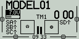
Экран 2 - стики, тумблеры и потенциометры
.png)
Экран 2 (Аппаратуры управления наземных моделей)
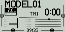
Экран 3 - Гистограмма каналов
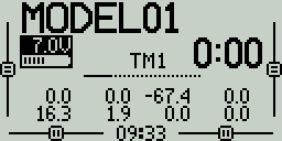
Экран 4 - Числовые значения каналов
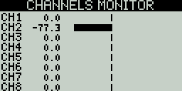
Экран 5 - монитор каналов и микшеров
Экраны
Экран 1 - На этом экране показаны: имя модели, позиция триммеров (если они включены), часы, напряжение батареи питания пульта, режим полёта, уровень сигнала на приёмнике и Таймеры 1 и 2 (если включены).
Экран 2 - На этом экране показаны: имя модели, позиция триммеров (если они включены), часы, напряжение батареи питания пульта, режим полёта, уровень сигнала на приёмнике и Таймер 1 (если включен). Также на нём графически показано положение стиков, потенциометров (крутилок) и положение тумблеров. Используйте [Ролик] или [Энкодер] для прокрутки между дополнительными страницами экрана. На второй странице показано состояние логических переключателей.
Экран 3 - На этом экране показаны: имя модели, позиция триммеров (если они включены), часы, напряжение батареи питания пульта, режим полёта, уровень сигнала на приёмнике и Таймер 1 (если включен). Кроме того, на нём графически показаны значения каналов управления в виде гистограммы, по 8 каналов на странице. Для прокрутки между страницами воспользуйтесь [Роликом].
Экран 4 - На этом экране показаны: имя модели, позиция триммеров (если они включены), часы, напряжение батареи питания пульта, режим полёта, уровень сигнала на приёмнике и Таймер 1 (если включен). Кроме того здесь показаны числовые значения каналов управления, по 8 каналов на странице. Для прокрутки между страницами воспользуйтесь [Роликом].
Экран 5 - На этом экране находится монитор каналов (channel monitor) или микшеров (mixer monitor), по 8 каналов на странице.Для прокрутки между страницами воспользуйтесь [Роликом]. Нажмите на [Ролик] чтобы переключиться между монитором каналов и монитором микшеров2.
Долгое нажатие на [Ролик] на одном из экранов Главного Вида откроет всплывающее меню со следующими пунктами:
- View Notes (Просмотр заметок)- Отображает настроенную для модели заметку/чеклист. Этот пункт виден, только если соответствующий текстовый файл (.txt с идентичным модели именем) находится в папке Models.
- Reset (Сброс) - См. страницу Сброс.
- Statistics (Статистика) - См. страницу Статистика.
- About (Информация) - Показывает версию (наименование) установленной прошивки EdgeTX.
Триммер или Трим (Trim) - это небольшой рычажок на пульте управления, который позволяет точно подстроить нейтральное положение стиков без изменения основных настроек, смещением значения управляющего сигнала на некоторое малое значение. Обычно их четыре, по числу каналов управления. При управлении квадрокоптерами они практически не используются, т.к. современные полётные контроллеры используют гироскопы и акселерометры, которые автоматически корректируют дрейф, и правильная калибровка важнее ручной подстройки (как и в современных моделях вертолётов). Однако, в радиоуправляемых самолётах и автомобилях триммеры (тримы) могут использоваться для уточнения центра рулевых поверхностей и компенсации дрейфа.
В нейтральном положении ползунки триммеров на ч/б экране имеют по две полоски.
\
Монитор каналов показывает финальные обработанные значения сигналов управления, которые передаются на приёмник модели. Монитор микшеров показывает промежуточные значения, после обработки микшерами, но до применения кривых и обрезки (клиппинга) значений, поэтому значения здесь могут превышать 100%.
Сброс (Reset)
Выбор пункта Сброс (Reset) во всплывающем меню, предлагает следующие варианты действий:
Сброс сессии (Reset flight) - Когда выбрано это действие:
- Все таймеры, настроенные с режимом постоянства1 Полёт сбрасываются до ноля.
- Сбрасываются значения всех обнаруженных датчиков телеметрии
- Сбрасывается текущее состояние всех логических переключателей
- Активируются те же проверки, что и при загрузке новой модели - т.е. позиция стика газа (throttle), положение тумблеров, проверка настройки режима failsafe2, отображение предполётного чеклиста, если настроено, проверка застрявших клавиш, и т.д.
Сбросить таймер (Reset timer) 1 / 2 / 3 - Сбрасывает только выбранный таймер, независимо от настройки режима постоянства
Сбросить телеметрию (Reset telemetry) - Сбрасываются значения всех обнаруженных датчиков телеметрии.
Режим постоянства (Persistence) определяет в каких случаях значение таймера сохраняется (чтобы продолжить отсчёт при возобновлении действия), а в каких оно сбрасывается до нулевого.
Failsafe (отказоустойчивость) — это функция, которая обеспечивает автоматическое выполнение заранее заданных действий в случае потери связи с передатчиком. Обычно это включает в себя возврат модели в безопасное положение или её плавную (или не очень) посадку, чтобы минимизировать риск аварии.
Статистика (Statistics)
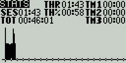
Экран статистики
Экран Статистика (Statistics) содержит статистические показатели использования вашей аппаратуры. Большинство данных сбрасывается при выключении аппаратуры. Доступны следующие показатели:
- SES - (Session) Время, в течение которого аппаратуры была включена (с последнего включения).
- THR - (Throttle) Время, в течение которого значение стика газа было выше 0%.
- TH% - (Throttle %) Время, в течение которого значение стика газа было выше 50%.
- TM1/2/3 - Значения Таймеров 1-3
- TOT - (Total) Общее время, в течение которого аппаратура была включена (с последнего сброса устройства)
Долгое нажатие на [Ролик] сбросит значения на экранах Статистики и Отладки (включая TOT).
Нажмите на кнопку [PAGE>] чтобы перейти на экран Отладка (Debug) (нажмите ещё раз для перехода на следующий экран отладки).
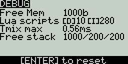
Экран отладки 1
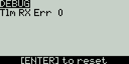
Экран отладки 2
Экран Отладка (Debug) содержит данные, используемые разработчиками при отладке работы программного обеспечения. Большинству пользователей не понадобится эта информация, кроме случаев совместного исследования проблем с разработчиками.
- Free mem - Текущая свободная память аппаратуры в байтах.
- Lua scripts (Lua скрипты)
- [D] - Максимальная длительность Lua, мс.
- [I] - Максимальный интервал Lua, мс.
- TMix max - Максимальная длительность задачи микширования.
- Free stack - [Menu] / [Mix] /[Audio]
- [Menu] - Минимальная свободная память стэка для задач меню.
- [Mix] - Минимальная свободная память стэка для задач микшеров.
- [Audio] - Минимальная свободная память стэка для задач аудио.
- Tlm RX Err - Количество полученных ошибок телеметрии.
Настройки модели (Model Settings)
Выбор Модели (Model Select)
Нажмите кнопку **[MDL]**из Главного вида, чтобы открыть экран Выбор Модели (Model Select).
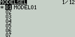
Экран Выбора Модели (Model Select)
Используйте [Ролик] для перемещения между ячейками в списке моделей.
Нажмите [Enter] (нажмите на ролик) в пустой ячейке в списке, чтобы открыть меню создания модели:
- Create Model (Создать модель) - Создать новую модель с настройками по умолчанию. This option creates a new model with the default configuration options.
- Restore Model (Восстан модель) - Создать новую копию модели, для которой ранее была создана резервная копия (появится список доступных резервных копий).
Нажмите [Enter] (нажмите на ролик) в ячейке с моделью, которая неактивна в данный момент1 (не отмечена звёздочкой *), чтобы открыть меню действий с моделью:
- Select Model (Выбор модели) - выбирает эту модель в качестве текущей активной.
- Backup Model (Резер копия модели) - сохраняет резервную копию модели в папке Backup на карте памяти.
- Copy Model (Копир модель) - создаёт копию выбранной модели и позволяет выбрать ячейку, в которую она будет сохранена.
- Move Model (Перемес модель) - позволяет переместить выбранную модель в другую ячейку.
- Delete Model (Удалить модель) - удаляет выбранную модель.
Нажмите [Enter] (нажмите на ролик) в ячейке с моделью, которая активна сейчас (отмечена звёздочкой *), чтобы открыть меню действий с активной моделью:
- Move Model (Перемес модель) - позволяет переместить выбранную модель в другую ячейку.
- Copy Model (Копир модель) - создаёт копию выбранной модели и позволяет выбрать ячейку, в которую она будет сохранена.
- Backup Model (Резер копия модели) - сохраняет резервную копию модели в папке Backup на карте памяти.
Нажмите на кнопку [PAGE>], чтобы перейти на экран Установки модели (Setup).
По сути, модель в EdgeTX - это набор различных настроек, заданный для управления определённой моделью (или рядом аналогичных моделей): используемый передатчик, протокол управления, номер модели и данные бинда (привязки), настройки микшеров, кривых и лимитов для каналов управления, таймеры, уведомления, настройки failsafe, триммеры и сабтримы, и т.д.
Выбор модели в качестве активной в EdgeTX означает применение всех её настроек к аппаратуре управления. Фактически, это загрузка нужного "профиля управления", который диктует, как пульт управления будет работать с радиоуправляемой моделью. Эти профили хранятся в формате yaml файлов, в папке MODELS на карте памяти аппаратуры.
Установки модели (Setup)
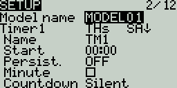
С экрана Setup (установки модели) начинается конфигурация любой модели. Экран содержит следующие настройки:
Name - Имя модели. Максимальная длина - 10 символов.
- Чтобы отредактировать символ в тексте, используя [ролик] или [поворотный энкодер], нажмите на него, прокрутите до нужной буквы, затем снова нажмите на ролик, чтобы перейти к редактированию следующего символа. Для переключения между строчными и заглавными буквами используйте долгое нажатие на ролик. Нажмите кнопку [RTN] для выхода из режима редактирования.
Image - Изображение, показываемое на экране Главного вида (только для пультов с дисплеем 212 x 64, напр. Taranis X9D).
Таймеры
Timer 1/2/3 - В EdgeTX доступны три настраиваемых таймера. Описанные ниже настройки таймера будут отображаться, когда режим таймера примет значение отличное от OFF (Выкл):
Timer 1 [Режим] [Тумблер]
[Режим] - Возможны следующие значения:
- OFF - Таймер не используется
- ON - Таймер запущен всегда
- Strt (Start) - Таймер запускается, когда активирован назначенный ему тумблер. После того как таймер запущен, положение тумблера уже не влияет на его работу.
- THs (Throttle) - Таймер запускается, когда стик газа поднят выше минимума и активирован назначенный ему тумблер. Таймер остановится, если стик газа опустится до минимального значения или назначенный тумблер будет выключен.
- TH% (Throttle %) - Таймер ведёт отсчёт пропорционально значению стика газа: при значении газа 100% отсчёт ведётся в реальном времени, при значении газа 50% - в два раза медленнее1.
- THt (Throttle Start) - Таймер запускается, когда стик газа поднят выше минимума и активирован назначенный ему тумблер. После того как таймер запущен, значение газа не влияет на его работу и остановится он только тогда, когда будет выключен назначенный ему тумблер.
[Тумблер] - Выберите тумблер, который будет отвечать за запуск таймера. Если тумблер не назначен, запуск таймера будет определяться только назначенным ему режимом. Помимо тумблера вы можете назначить: триммер, датчик телеметрии (запускает таймер при получении данных телеметрии от этого датчика), физическое действие (движение стика или нажатие кнопки) (пометка ACT).
Name - Имя таймера
Start - Здесь задаётся временное значение, используемое для расширенных функций таймера. Значение по умолчанию 00:00, если его не менять, то таймер будет работать как секундомер - отсчитывать время с момента запуска, пока не будет остановлен. Если ввести в этом поле значение отличное от ноля, то рядом появится дополнительное поле, которое может принимать два значения:
Remain (Остал) - таймер будет вести обратный отсчёт от заданной величины до ноля и выдаст оповещение пользователю по окончании.
Elaps (Прошло) - таймер работает как "будильник", ведя отсчёт от ноля до заданной величины и затем оповещая пользователя.
Persist. или Persistence (Режим постоянства):
- OFF (Выкл) - Значение таймера сбрасывается при переключении модели или при выключении/включении аппаратуры.
- Flight (Полет) - Значение таймера НЕ сбрасывается при переключении модели или выключении аппаратуры. Таймер сбрасывается только когда пользователь выберет действие Сброс сессии (Reset session) в меню Сброс (Reset).
- Manual Reset (Руч сброс) - Значение таймера сбрасывается только когда пользователь сбрасывает выбранный таймер (напр. Сбросить таймер1 (Reset timer1)) в меню Сброс (Reset).
Minute или Minute Call (Минут) - Если выбрано, то таймер будет выдавать оповещения каждую прошедшую минуту согласно настройке Countdown (Обратный отсчёт) option.
Countdown (Обратный отсчёт):
- Silent (Без звука) - пульт не выдаёт оповещений, пока таймер не достигнет нулевого значения. Когда это произойдёт, вы услышите звуковой сигнал.
- Beeps (Сигн) - пульт будет выдавать звуковой сигнал каждую секунду, начиная с момента, когда до окончания таймера останется (5,10,20,30) секунд - эта величина задаётся в соседнем поле.
- Voice (Голос) - пульт будет вести посекундный обратный отсчёт времени, начиная с заданной величины оставшегося времени.
- Haptic (Вибро) - пульт будет выдавать вибросигнал каждую секунду, начиная с заданной величины оставшегося времени.
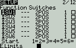
Настраиваемые переключатели
Function Switches (Настраиваемые тумблеры)
Этот пункт меню доступен только на некоторых моделях, оборудованных специальным набором кнопок (например, ряд из 6 кнопок на Jumper T-Pro). Логичнее было бы назвать его настраиваемые кнопки, этим наименованием мы и будем пользоваться дальше. Если вы не видите его на странице установок модели, перейдите к следующему пункту ниже на странице.
Настраиваемые кнопки - это вид многопозиционного переключателя (на некоторых пультах управления), поведение которого может полностью определяться настройками. Физически это выглядит как ряд кнопок или 6-позиционный переключатель, но возможности такого переключателя гораздо более гибкие. Например, на Radiomaster TX16S или Radiomaster Boxer есть обычный 6-позиционный переключатель, но он не является программно-настраиваемым, поэтому на этих пультах нет такого пункта меню, а сам переключатель отображается как потенциометр на вкладке Hardware.
В отличие от других переключателей, поведение которых задаётся на уровне настроек аппаратуры, поведение настраиваемых кнопок задаётся на уровне модели и настраивается на экране настроек модели. Доступны следующие поля:
Имя
Каждой из кнопок можно задать трёхсимвольное имя в поле "---" рядом с обозначением переключателя.
Тип кнопки
- None: кнопка отключена
- Toggle: кнопка без фиксации, считается включенной только пока нажата
- 2POS: кнопка с фиксацией, нажатие изменит состояние между Вкл и Выкл
Группа
Обычный 6-позиционный переключатель - это группа из 6 кнопок, работающих вместе, где только одна из шести может быть нажата в данный момент. Настраиваемые кнопки расширяют этот функционал и позволяют вам решать, как будут сгруппированы между собой отдельные кнопки.
'-' означает кнопку, не входящую в какую-либо группу. Нажатие меняет только её состояние.
'1', '2' или '3' задаёт группу. Все кнопки в группе работают вместе, т.е. только одна (последняя нажатая) кнопка может считаться активной.
Всегда вкл (Always on) группа
Галочка в этом поле заставляет группу кнопок работать как обычный 6-позиционный переключатель (или n-позиционный, т.к. кнопок в группе может быть меньше 6), т.е. одна кнопка из группы всегда должна быть нажатой (Вкл).
Стартовая позиция
Start - Определяет состояние, в котором окажется каждая кнопка, когда модель будет загружена.
- ↑ Кнопка не нажата (выкл)
- ↓ Кнопка нажата (вкл)
- = Кнопка находится в том же состоянии, в котором она была в последний раз, когда использовалась эта модель(сохраняет состояние между переключениями).
Trims (Триммеры/Тримы)
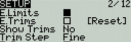
Настройки тримов
E.Limits (Расширенные лимиты) - включение этой опции расширяет диапазон выходного сигнала канала управления от -150 до 150. Расширенные лимиты необходимы, когда стандартных лимитов недостаточно для достижения полного хода рулей управления.
E. Trims (Расширенные тримы2) - Увеличивает максимальную величину корректировки (триммирования) с ±25% до ±100%.
Reset - Сбрасывает все поправки (тримы) до ноля.
Show trims (Показать тримы) - Если выбрано Yes, то на индикаторах триммирования на экране устройства будут показываться численные значения тримов. Если выбрано CHANGE, то численные значения будут показываться только для тримов, отличных от ноля.
Trim Step (Шаг триммирования) - Опеределяет величину смещения, задаваемого одним нажатием на триммер на аппаратуре:
- Coarse (Грубо) = 1.6%
- Medium (Средне) = 0.8%
- Fine (Мелко) = 0.4%
- Extra Fine (Очень мелко) = 0.2%
- Exponential (Экспо) = 0.2% около центрального положения триммера, значение шага увеличивается экспоненциально при увеличении значения отклонения
Throttle (Газ)
.png)
Настройки газа
Настройки, связанные со стиком газа, отображаются в раскрывающемся меню.
T-Reverse (Реверс) - Когда включено, выходные значения управляющего канала газа меняются на обратные (от макс к мин).
T-Source (Источник) - Задаёт источник (т.е. стик или элемент управления), который будет определять значение газа.
T-Trim-Idle (Только трим холостого хода) - Когда включено, заданное триммирование газа будет применяться только на нижней половине хода стика газа.
T-Trim-SW (Триммер переключатель) - определяет, какой триммер на аппаратуре будет задавать триммирование газа. Возможно, например, переназначить триммеры крена, тангажа или рысканья на управление триммированием газа.
Pre-start Checks (Предстартовые проверки)
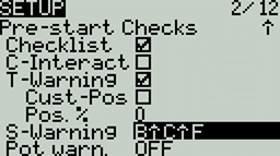
Настройки предстартовых проверок
Каждый раз, когда активируется новая модель (переключается текущая), EdgeTX выполняет ряд предстартовых проверок, заданных на этой странице. Если какая-то из проверок не будет пройдена, EdgeTX выдаст звуковое и экранное предупреждение, и пользователь должен будет подтвердить своё намерение, чтобы продолжить использовать модель. Следующие настройки проверок доступны в раскрывающемся меню:
Checklist (Контрольный список/Чеклист) - когда включено, соответствующие модели заметки будут показаны на экране при загрузкt модели. Соответствующий текстовый файл (.txt с идентичным модели именем, напр Mobula8.txt) должен находиться в папке Models на карте памяти. Содержание фала - на усмотрение пользователя.
C-Interact (Interactive checklist/Интерактивный чеклист) - эта опция используется вместе с предыдущей настройкой Checklist. Когда выбрано, то каждая строка текста в файле заметок, начинающаяся со знака "равно" = будет показана как чекбокс (поле для галочки) при отображении чеклиста. Для того, чтобы закрыть чеклист и пройти этот шаг проверки, пользователь обязан проставить галочки во всех чекбоксах (нажатием на ролик или Enter).
T-Warning (Газ-предупреждение) - когда выбрано, аппаратура будет проверять, что значение газа соответствует минимальной величине (стик в нижнем положении) для источника, указанного в настройке T-Source (см. выше).
Cust-Pos (Своё положение) - если отмечено, то величина параметра Pos. % будет использоваться для предупреждения о уровне газа T.Warning.
Pos. % - минимальное значение стика газа, при котором будет выдаваться предупреждение "Throttle warning", если отмечена опция Cust-Pos.
S-Warning (Предупреждение о позиции тумблеров) - Этот раздел отображает все тумблеры, сконфигурированные на пульте, и позволяет задать требуемую стартовую позицию для каждого тумблера, которая и будет проверяться при загрузке модели. Выбрав тумблер, прокрутите индикаторы положения до требуемого или отключите проверку совсем.
Pot warn. (Положение потенциометра) - когда отмечено, производится проверка положения потенциометров и слайдеров. Доступно три варианта - OFF, ON и Auto. Когда выбран вариант ON или AUTO, появляются индикаторы соответствующих потенциометров и слайдеров. Чтобы включить предупреждение о положении потенциометра, выберите его с помощью [ролика] и нажмите чтобы выделить его. Проверка включена для выделенных потенциометров.
- OFF - положение потенциометров или слайдеров не проверяется.
- ON- положение потенциометров сравнивается с положением, заданным пользователем вручную. Чтобы вручную установить требуемое положение для проверки, с помощью ролика выберите нужный потенциометр в списке справа, установите сам потенциометр в нужное положение, и долгим нажатием на [Ролик или Enter] сохраните текущую позицию для проверки.
- Auto - положение потенциометров сравнивается с последним автоматически сохранённым значением перед выключением аппаратуры или переключением модели.
Ctr Beep (Звук на центре) - позволяет вам включить или отключить звуковой сигнал, когда стик или потенциометр находятся в центральной позиции. Для этого нужно выбрать нужный элемент управления [роликом] и коротким нажатием выделить элемент. Сигнал прозвучит, когда выделенный элемент управления займёт центральное положение. (R - рысканье, Е - тангаж, Т - газ, А - крен, 1 2 - потенциометры S1 S2)
Glob. Funcs (Глобальные функции) - Когда выбрано, глобальные функции, заданные в настройках аппаратуры, будут применяться к текущей модели. При отключении, глобальные функции не будут применяться к модели.
ADC filter (Фильтр АЦП) - Включает/отключает АЦП фильтр для текущей модели. Значение Global применит к модели глобальное значение из настроек аппаратуры, которое по умолчанию включено.
Internal RF и External RF (Внутренний и внешний передатчик)
Настройки внутреннего и внешнего радиопередающих модулей аналогичны, с той разницей, что раздел Internal RF используется для конфигурации передатчика встроенного внутри вашей аппаратуры управления, а раздел External RF конфигурирует внешний передатчик, который обычно приобретается отдельно и вставляется в специальный JR3 отсек на вашей аппаратуре.
Варианты режима работы (Mode): OFF (Выкл) или имя модуля установленного внутри аппаратуры управления (согласно настройкам аппаратуры на вкладке аппаратных настроек (Hardware)) или протокол управления внешнего модуля. Набор настроек уникален для каждого модуля, пожалуйста обратитесь к документации производителя для конкретного набора настроек. В большинстве случаев, если включен один из передатчиков, другой должен быть отключен. Для тренировки в симуляторе стоит отключить оба передатчика.
Ниже приведён пример настроек внешнего модуля Radiomaster Bandit ELRS:
Mode - протокол общения между аппаратурой и передатчиком (используется CRSF, т.е. протокол Crossfire, изначально разработанный компанией TeamBlackSheep)
Baudrate - скорость передачи данных между аппаратурой и внешним передатчиком на аппаратном уровне. Стандарт для современного CRSF - 420 КБод/с. Диапазон возможных значений зависит от аппаратной реализации как аппаратуры управления, так и радиопередающего модуля (внутреннего или внешнего).
Status - здесь определяет режим работы передатчика, в первую очередь скорость передачи пакетов данных (packet rate) протокола ELRS от внешнего передатчика к приёмнику модели, т.е. скорость обмена данными между пультом управления и моделью. Максимум возможного значения в этом поле определяется в первую очередь двумя факторами:
- Несущей частотой передатчика и приёмника управления. Например, системы ELRS, работающие на несущей на частоте 900 МГц, ограничены частотой передачи пакетов в 250 Гц, а системы ELRS на несущей частоте 2.4 ГГц поддерживают расширенные режимы передачи пакетов данных с частотой до 1000 Гц.
- Заданным ранее Baudrate, т.е. скоростью обмена данными между аппаратурой управления и передатчиком. Например, в системах ELRS скорость передачи пакетов 500 Гц требует baudrate не ниже 400 КБод/с, а baudrate 115200 бод/с ограничивает скорость передачи пакетов до 250 Гц.
Ch. Range - диапазон используемых каналов управления
Настройки для ELRS модуля описаны здесь (англ.): https://www.expresslrs.org/quick-start/transmitters/tx-prep/
Receiver number (Номер приёмника) - это номер, назначаемый данной модели пользователем. Этот номер отправляется на приёмник модели после завершения процедуры привязки (бинда) передатчика и приёмника. Номер, назначаемый модели, должен быть уникальным, хотя может совпадать для моделей использующих разные протоколы управления. EdgeTX сообщит вам является номер приёмника уникальным или уже используется другой моделью, с помощью текста над полем номера приёмника.
Trainer (Тренер)
Mode - настройка режима работы тренерского разъёма, здесь можно настроить режим и способ сквозной передачи данных CPPM4. Когда включена, эта настройка позволяет передавать CPPM сигналы управления от аппаратуры, работающей в режиме Slave (ведомого) к другой аппаратуре, работающей в режиме Master (Ведущего), которая затем передаст этот сигнал радиоуправляемой модели, к которой она подключена. Сквозная передача CPPM может использоваться в разных случаях: подключение датчика отслеживания движений головы, работа инструктора с учащимся, контроль технически сложных моделей, для управления которыми требуется больше переключателей, чем доступно на стандартном пульте.
Master mode (Режим ведущего) - Этот режим выбирается на аппаратуре, которая будет непосредственно подключена к модели. На этой аппаратуре также необходимо настроить специальную/глобальную функцию (Тренер), позволяющую активировать сквозную передачу данных по тумблеру/кнопке. Когда ведущий включит сквозную передачу данных, CPPM сигнал управления от ведомого пульта (находящегося в режиме Slave mode ) будет через передаваться на модель через передатчик ведущего.
Slave mode (Режим ведомого) - Этот режим для той аппаратуры (ученика), которая будет передавать свой сигнал управления CPPM на ведущую (в режиме Master mode,), которая уже передаст их на радиоуправляемую модель.
Ниже возможные варианты настроек:
- OFF - Режим Тренера не используется в этой модели.
- Master/Jack - Режим ведущего через проводное соединение. Master mode using a cable connection.
- Slave/Jack - Режим ведомого через проводное соединение.
- Ch. Range - Определяет диапазон каналов управления, которые будут передаваться от ведомого к ведущему. Не рекомендуется использовать каналы выше десятого.
- PPM frame - Формат кадра (последовательности импульсов) PPM. Первое поле - длина РРМ-кадра. Второе поле – это длина стоп-сигнала / задержка между импульсами. Выпадающий список позволяет выбрать полярность сигнала. Длина кадра автоматически подстраивается под количество передаваемых каналов, но её можно изменить вручную. Примечание: В большинстве случаев, менять значение по умолчанию не требуется.
- Master / Bluetooth - Режим ведущего через беспроводное соединение Bluetooth (если установлено в аппаратуре)
- Slave / Bluetooth - Режим ведомого через беспроводное соединение Bluetooth (если установлено в аппаратуре)
- Master / Multi - Режим ведущего через беспроводное соединение посредством внешнего мультипротокольного модуля. Подробнее см Настройка режима тренера с помощью мультипротокольного модуля
Enabled Features (Включенные Функции)
.png)
Enabled Features options
Раздел Enabled Features позволяет настроить видимость определённых вкладок (страниц) на экранах настроек аппаратуры и настроек модели, для текущей модели. Названия вкладок отображаются в раскрывающемся меню со следующими вариантами видимости:
- Global - видимость определяется глобальным значением, заданным в разделеEnabled Features на экране Radio Setup (Настройки аппаратуры). На экране настроек аппаратуры глобальное значение указано галочкой рядом с именем страницы (Вкл/Выкл).
- On - эта вкладка будет видна при загрузке текущей модели.
- Off - эта вкладка не будет видна при загрузке текущей модели.
Исключение: Отключение видимости вкладки "Global / Special Functions" (Глобальные / Специальные функции) отключит настроенные глобальные / специальные функции для этой модели.
USB Joystick (USB Джойстик)
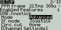
Настройки расширенного режима USB Джойстика
USB Джойстик имеет два возможных режима настройки: Classic (Классический) и Advanced (Расширенный).
В Классическом режиме, значения настроенных на пульте каналов управления передаются на целевое устройство (напр. компьютер) согласно порядковому номеру канала и сопоставляются с предварительно настроенными осями и кнопками USB-контроллера устройства. Ниже описано соответствие каналов и осей/кнопок для Microsoft Windows.
- Ch 1 - Ось X
- Ch 2 - Ось Y
- Ch 3 - Ось Z
- Ch 4 - Вращение по оси X
- Ch 5 - Вращение по оси Y
- Ch 6 - Вращение по оси Z
- Ch 7 - Энкодер
- Ch 8 - Слайдер
- CH 9 - Ch 32 - Кнопки 1 - 24
В Расширенном режиме вы можете настроить дополнительные параметры:
If. mode (Interface mode) (Режим интерфейса): Это указывает целевому устройству (устройству, к которому вы подключаете ваш передатчик), какой тип устройства вы подключаете. Доступные варианты: Joystick, Gamepad, MultiAxis (Джойстик, Геймпад, Многоосевое устройство).
Circ. cut (Circular cutout) (Круглый вырез) - Это настройка ограничения диапазона движения по парам осей. Для пар осей (X-Y, Z-rX): по умолчанию диапазон движения стика представляет собой прямоугольную область. С этой опцией, движение по оси будет программно ограниченно круглой областью (как на обычных геймпадах). Возможные значения: None или X-Y, Z-rX или X-Y, rX-rY или X-Y, Z-rZ.
Channel Settings (Настройки каналов)
Mode - Вы можете назначить режим работы для каждого выходного канала. Доступные варианты: None, Btn, Axis, Sim.
- None - Канал не используется
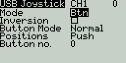
Настройки канала для режима Кнопки
- Btn - Канал используется для симуляции кнопки. Возможные настройки:
- Inversion - Инверсия выходного сигнала (Вкл / Выкл)
- Button Mode (Режим кнопки)
- Normal - Каждое положение многопозиционного переключателя представлено кнопкой. Текущее состояние переключателя представлено зафиксированной в нажатом положении кнопкой.
- Pulse - Схоже с предыдущим режимом, но текущее состояние представлено кратковременным нажатием на соответствующую кнопку.
- SWEmu - Тумблер эмулирует кнопку с фиксацией положения. Первое нажатие включает виртуальную кнопку, второе отключает.
- Delta - Изменение значения выходного канала представлено двумя виртуальными кнопками. При уменьшении значения - нажата первая кнопка, при увеличении - вторая. Если значение канала не меняется - ни одна из кнопок не нажата.
- Companion - используется для контроля симулятора при подключении к EdgeTX Companion. Позволяет корректно обрабатывать нажатия многопозиционного переключателя в симуляторе.
- Normal - Каждое положение многопозиционного переключателя представлено кнопкой. Текущее состояние переключателя представлено зафиксированной в нажатом положении кнопкой.
- Positions - Тип эмулируемой кнопки.
- Push - канал соответствует одной кнопке
- 2POS - 8 POS - количество позиций переключателя соответствует количеству эмулируемых кнопок (напр. трёхпозиционный тумблер будет соответствовать трём кнопкам).
- Push - канал соответствует одной кнопке
- Button No: Номер кнопки на целевом устройстве, к которой будет привязан канал управления.
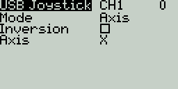
Настройки осевого режима для выбранного канала
- Axis - Канал используется для симуляции движения по оси и будет привязан к одной из осей по умолчанию целевого устройства
- Варианты настроек оси: X, Y, Z, rotX (вращение по X), rotY, rotZ
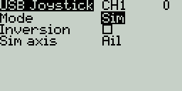
Настройки осевого режима симулятора (Sim) для выбранного канала
- Sim - Канал используется для симуляции одной из общеиспользуемых осей в симуляторе и будет отображаться на целевом устройстве согласно выбранному варианту (напр Thr, Throttle, т.е. Газ):
- Варианты настройки осевого режима симулятора: Ail (крен), Ele (тангаж), Rud (рысканье), Thr, Acc (газ), Brk (Тормоз), Steer (Руление), Dpad (крестик управления джойстика)
Нажмите на кнопку [PAGE>] для перехода на экран Вертолётные установки (Heli Setup).
Режим Throttle% позволяет приближённо учитывать расход аккумулятора (или топлива) модели в тех случаях, когда телеметрия недоступна. Например, зная среднее время полного расхода аккумулятора (бака) в режиме 50% газа, можно установить Таймер 1 в режим Throttle%, задать ему известное вам время*2(*0.9 для запаса времени на посадку), настроить работу в режиме обратного отсчёта и установить голосовое оповещение по окончании. Тогда вы получите оповещение приблизительно в тот момент, когда израсходуете 90% заряда(топлива) вашей модели.
Триммер (Trim tab, от англ. trim – подрезать, подправлять) - в авиации, это небольшая отклоняющаяся поверхность в хвостовой части руля или элерона летательного аппарата. В реальных самолётах, триммирование (trimming) означает подстройку аэродинамических рулей (например, с помощью триммерных закрылков), чтобы уменьшить нагрузку на пилота и держать самолёт в нужном положении без постоянного отклонения штурвала. В RC-моделях подобная коррекция может задаваться на уровне аппаратуры управления, смещая значение управляющего сигнала на некоторую величину и позволяя точно настроить нейтральное положение сервоприводов управления. Часто такие смещения называют просто Тримы, отличая их от Триммеров, т.е. физических переключателей, задающих эти смещения.
JR Module Bay – это стандартный разъём для сменных RF-модулей в передатчиках, который был изначально разработан компанией Japan Remote Control (JR). Он позволяет менять передающую систему без замены всей аппаратуры. Имеет несколько форм-факторов: стандартный Full-size, micro и nano.
Combined Pulse Position Modulation - комбинированная импульсно-позиционная модуляция, способ передачи данных, позволяющий передавать данные множества каналов по одному проводу, что позволяет использовать довольно простое однопроводное соединение между тренером и учеником.
Вертолётные установки (Heli Setup)
Страница вертолётных настроек Heli Setup в разделе Настройки Модели не является необязательной и доступна в сборках EdgeTX, собранных с флагом компиляции -DHELI=YES. Эта страница часто используется для настройки микширования циклического/коллективного шага лопастей (CCPM), используемого в радиоуправляемых вертолётах с сервоосью (flybar, система Белла-Хиллера), где приёмник напрямую управляет сервоприводами тарелки автомата перекоса (swashplate). Большинство моделей c традиционным автоматом перекоса без сервооси (flybarless, FBL, система Белла) не требуют настройки значений на этой странице. Выходы CCPM микшера (CYC1, CYC2, и CYC3) должны быть привязаны к каналам управления на экране Миксы.
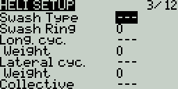
Вертолётные установки
Для настройки доступны следующие параметры:
- Swash Type - Тип автомата перекоса. Тип определяется углом расположения сервоприводов автомата перекоса относительно друг друга. Это влияет на способ управления коллективным и циклическим шагом винта вертолёта и определяет как передатчик будет микшировать управляющие сигналы. Доступные типы: 120, 120x, 140, and 90. (90 для механических систем, 120 самый популярный для электронного смешивания CCPM)
- Swash Ring - Задаёт ограничение хода тарелки автомата перекоса, настраивается только при необходимости (если есть механические проблемы). 1 = максимальное ограничение -> 100 или 0 = ход без ограничений.
- Long. cyc. source (Longitudinal cycle source) - Выбор источника управления по продольной оси (тангаж).
- Weight - Задаёт процентное значение соответствия хода стика и управляющего сигнала.
- Lateral cyc.source (Lateral cycle source) - Выбор источника управления по поперечной оси (крен).
- Weight - Задаёт процентное значение соответствия хода стика и управляющего сигнала.
- Coll. pitch source (Collective pitch source) - Выбор источника управления коллективным шагом (газ)
- Weight - Задаёт процентное значение соответствия хода стика и управляющего сигнала.
Нажмите кнопку [PAGE>] чтобы перейти на экран Режимы полёта (Flight Modes).
Режимы Полёта / Вождения (Flight / Drive Modes)
Режимы Полёта (FM) и Режимы Вождения (DM) (на аппаратурах управления наземными моделями, напр. Radiomaster MT12) позволяют применять разные настройки триммирования для каждого режима. После того как разные режимы полёта/вождения настроены, вы можете корректировать тримы1 (поправки) в каждом режиме, не влияя на настройки триммирования в других режимах (если только для них не настроены зависимости). Доступно 9 возможных настроек режимов полёта/вождения, Режим 0 используется по умолчанию.
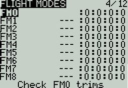
Обзорный экран режимов полёта
На обзорном экране режимов полёта/вождения показана следующая информация для каждого режима:
- Mode # - Номер режима
- Mode Name - Имя режима
- Switch - Переключатель, активирующий режим
- Trim settings (RETA) - настройки тримов каналов управления (порядок RETA: рысканье тангаж газ крен)
Check FM# Trims: (Проверка тримов выбранного режима) Выбор этого действия (ролик/ENTER) временно отключит все тримы текущего режима полёта. Это используется для проверки влияния текущих тримов на выходные значения каналов управления. Нажмите RTN для возврата на обзорный экран.
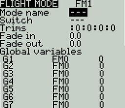
Экран конфигурации Режима Полёта
Выберите режим полёта на обзорном экране, чтобы открыть страницу конфигурации режима, на которой доступны следующие настройки:
Name: Пользовательское имя режима полёта. Если вы зададите значение в этом поле, то оно будет отображаться в левом верхнем углу главного экрана, рядом с уровнем заряда батареи.
Switch: Переключатель (и его положение), который включает этот полётный режим. Может использоваться: тумблер, потенциометр, телеметрия, триммер или логический переключатель.
Trims - Нажатием выберите колонку, соответствующую тримеру, который вы хотели бы изменить (порядок колонок: Т1 - Т4 или RETA). Затем прокрутите значения роликом, чтобы выбрать полётный режим (0-8), из которого будут взяты базовые значения тримов, и модификатор для этих значений (= or +, знак равенства на вашей аппаратуре может быть обозначен как :). Выберите значение -- чтобы отключить этот триммер в настраиваемом режиме полёта.
Если вместо полётного режима (0-8) выбрать 3P, то соответствующий триммер в выбранном режиме будет работать как трёхпозиционный переключатель без фиксации положения.
Модификатор - Модификатор = (или :) использует в настраиваемом Режиме значение трима непосредственного из указанного в соответствующей колонке Режима Полёта. Модификатор + берёт значение трима из указанного в колонке Режима Полёта и прибавляет к нему значение трима выбранного полётного режима (того, который вы настраиваете).
Пример 1: Если вы настраиваете полётный режим FM1 и в поле Trim в колонке триммера Т1 указали значение =0, трим Т1 в режиме полёта FM1 будет иметь то же значение, что задано для режима FM0. В этом случае изменения трима Т1 в режиме FM1 поменяют значение этого трима в FM0, и наоборот.
Example 2: Если вы настраиваете полётный режим FM1 и выставляете в поле Trim значение +0, то итоговое значение трима в FM1 будет равно значению из FM0 + дополнительные поправки, внесённые во время работы в режиме FM1. В таком случае, изменения тримов в FM1 не повлияют на значения в FM0; но изменения в FM0 повлияют на итоговые значения в FM1.
Fade in: Плавное изменение настроек триммирования при включении этого полётного режима. Укажите время в секундах (0.0 - 25.0) за которое новые значения тримов будут полностью применены.
Fade out: Плавное изменение настроек триммирования при выключении этого полётного режима. Укажите время в секундах (0.0 - 25.0) за которое новые значения тримов будут полностью применены.
Глобальные переменные (Global Variables)
Вы можете задать глобальные переменные, значения которых будут общими для всех экранов настроек модели. Эти значения можно использовать в весах, смещениях, дифференциалах, настройках экспонент, выходах и сравнениях для логических переключателей. Нижняя часть экрана конфигурации полётного режима показывает обзор всех глобальных переменных для выбранного режима полёта, со следующей информацией:
- Номер глобальной переменной: Номер переменной, отображаемый как GV(1-9)
- Имя глобальной переменной: Пользовательское имя глобальной переменной - до трёх символов.
- Режим: Определяет, откуда берётся значение глобальной переменной. Возможны следующие варианты:
- Own: Собственное значение переменной для выбранного режима полёта, оно вручную задаётся в поле Значение. (Для режима FM0 доступен только этот вариант)
- FM(1-9) - значение глобальной переменной наследуется из указанного полётного режима.
- Значение: Текущее значение глобальной переменной.
Вы можете отредактировать значение глобальной переменной в соответствующем поле. Если вы выберете номер глобальной переменной и нажмёте на ролик/Enter, откроется экран конфигурации глобальной переменной со следующими параметрами:
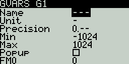
Экран конфигурации глобальной переменной
- Name - Пользовательское имя глобальной переменной - до трёх символов.
- Unit - (необязательное) Позволяет добавить символ % к отображаемому значению глобальной переменной. Это НЕ ВЛИЯЕТ на то, как вычисляются значения.
- Precision - Позволяет задать точность значения переменной как целочисленную (0.-) или как число с десятичным разрядом (0.0). Значение по умолчанию 0.-
- Min - Определяет разрешённый минимум значения глобальной переменной.
- Max - Определяет разрешённый максимум значения глобальной переменной.
- Popup - Если отмечено, всплывающее окно будет появляться на главном экране при изменении значения этой переменной в процессе обычного использования.
- FM1 -> FM8 - Позволяет выбрать режим наследования редактируемой глобальной переменной для различных полётных режимов. Долгое нажатие на соответствующем поле переключает режим наследования между Own и Inheritence(Наследование). В режиме Own вы можете задать своё значение для переменной в соответствующем полётном режиме. В режиме Наследования, вы можете выбрать полётный режим из которого будет унаследовано значение переменной.
Нажмите на кнопку [PAGE>] чтобы перейти на экран Входы (Inputs).
Триммер (Trim tab, от англ. trim – подрезать, подправлять) - в авиации, это небольшая отклоняющаяся поверхность в хвостовой части руля или элерона летательного аппарата. В реальных самолётах, триммирование (trimming) означает подстройку аэродинамических рулей (например, с помощью триммерных закрылков), чтобы уменьшить нагрузку на пилота и держать самолёт в нужном положении без постоянного отклонения штурвала. В RC-моделях подобная коррекция может задаваться на уровне аппаратуры управления, смещая значение управляющего сигнала на некоторую величину и позволяя точно настроить нейтральное положение сервоприводов управления. Часто такие смещения называют просто Тримы, отличая их от Триммеров, т.е. физических переключателей, задающих эти смещения.
Входы, Миксы и Выходы (Inputs, Mixes & Outputs)
Для того чтобы поддерживать множество различных типов пультов управления, EdgeTX использует универсальную схему обработки данных, применимую к любой аппаратуре управления.
В этой схеме любой физический элемент управления аппаратуры (стики, тумблеры, слайдеры, потенциометры) может быть привязан ко Входу в программном обеспечении аппаратуры.
Входные данные могут быть преобразованы и переданы дальше или скомбинированы с другими Входами в один Микс.
Далее, эти Миксы могут быть изменены путём применения весов, смещений и кривых и назначены на Выход канала управления.
Перед тем как данные отправятся в модуль передатчика, к Выходам применяются финальные преобразования (включая субтриммеры, кривые, предельные и центральные значения).
Ниже представлена блок-схема, в общих чертах описывающая модель обработки управляющих сигналов в EdgetX. Более подробная информация находится в разделах Входы (Inputs), Миксы (Mixes) и Выходы (Outputs).
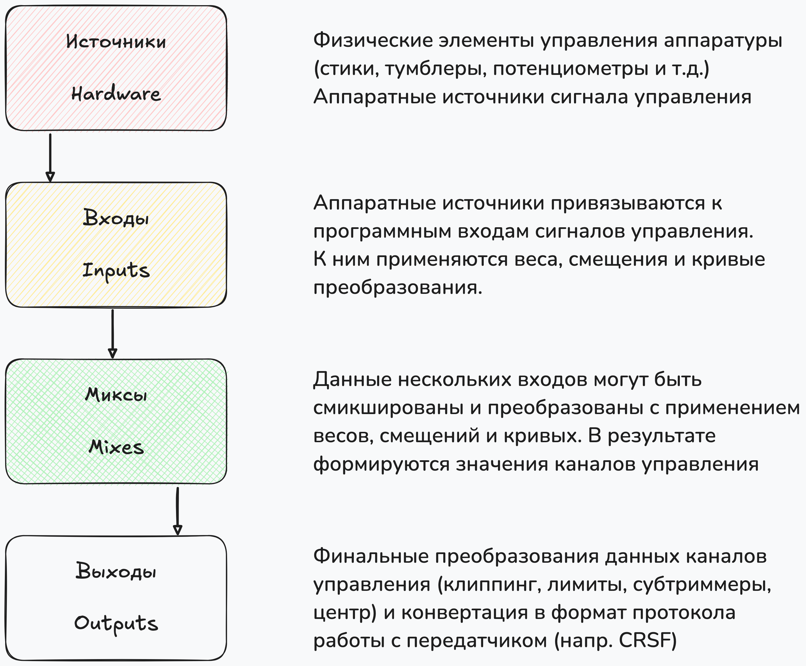
Схема обработки управляющих сигналов в EdgeTX
Входы (Inputs)
На экране Входы (Inputs) можно назначить физические элементы управления (стики, слайдеры, потенциометры) или датчики телеметрии на программные Входы микшера сигналов управления1. После того как физический управляющий сигнал (или сенсор телеметрии) назначен на программный вход микшера, к нему можно применить модификаторы, такие как вес (также называемый расход), смещение или кривые - итоговое входное значение изменится для всех миксов (микшеров), использующих этот программный Вход.
Хотя и возможно назначить кнопки и тумблеры в качестве источников для программных Входов, обычно это не требуется, т.к. к ним очень редко применяются модификаторы (вес, смещение, кривые). По умолчанию, EdgeTX автоматически назначит стики на каналы управления Крен, Тангаж, Газ, Рысканье (Aileron, Elevator, Throttle, Rudder) согласно порядку каналов управления по умолчанию, заданному на экране Настройка Пульта (Radio Setup).
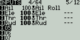
Экран Входы
На экране Входы находится список всех настроенных программных Входов (I - Input) и их входных линий2. Каждая строка представляет собой входную линию микшера и содержит следующую информацию слева направо: имя (или порядковый номер) Входа для которого настроена входная линия, вес линии (расход), источник управляющего сигнала - физический элемент управления, имя входной линии, переключатель, активирующий эту линию. Эти пункты описаны в разделе Страница конфигурации Входа ниже.
Выберите настроенную входную линию и нажмите на [Ролик(Enter)] чтобы переключиться между режимами Копировать/Вставить (Copy/Paste) (линия выделена сплошной заливкой) и Переместить (Move) (линия выделена заливкой с пунктирным контуром). В режиме Copy/Paste создаётся копия входной линии, которая может быть вставлена на требуемую позицию в текущем или другом Входе. В режиме Move, выбранная линия может быть перемещёна на другую позицию в текущем или другом Входе. Воспользуйтесь роликом пульта для выбора позиции на которую будет скопирована/перемещена входная линия. Нажмите на кнопку [Return] для выхода из этого режима.
Выбор пустой строки и нажатие на [Enter] создаст новый программный Вход и откроет Страницу конфигурации Входа.
Выбор существующей линии и долгое нажатие на [Enter] откроет меню со следующими действиями:
- Edit - открывает Страницу конфигурации Входа для этой входной линии.
- Insert before - вставляет новую входную линию выше выбранной, в том же Входе.
- Insert after- вставляет новую входную линию ниже выбранной, в том же Входе.
- Copy - копирует выбранную входную линию, после чего с помощью Ролика можно выбрать позицию, на которую будет добавлена копия.
- Move - выбирает входную линию для перемещения, после чего с помощью Ролика можно выбрать позицию, на которую будет перемещена линия.
- Delete - удаляет выбранную входную линию.
Страница конфигурации Входа
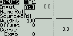
Страница конфигурации Входа
На Странице конфигурации Входа вы можете редактировать параметры выбранной входной линии. Справа от списка параметров находится активный график, показывающий как изменяется кривая значений Входа в зависимости от изменяемых параметров.
Input - Имя программного Входа, не более трёх символов.
Name - Имя входной линии Входа. Разные физические элементы управления могут служить источником сигнала для одного программного Входа, путём добавления дополнительных входных линий к существующему Входу. Один и тот же физический элемент управления может служить источником значений для нескольких входных линий одного Входа, имеющих разные настройки веса (расхода) на каждой линии - отсюда старое название Двойные Расходы (Dual Rates). Но только одна входная линия может быть активна на одном Входе, та для которой выполняется условие активации (см. параметр Switch ниже). Если условие активации выполняется для нескольких входных линий одного Входа, то активной будет та, что находится выше в списке.
Source - Источник управляющего сигнала, физический элемент управления аппаратуры. Помимо физических элементов управления, вы можете использовать значения MAX (всегда возвращает 100), MIN (всегда возвращает -100), CYC1-3 (выходы внутреннего CCPM микшера, настраиваемого на вкладке Heli, для некоторых моделей вертолётов), триммеры, значения каналов и другие. Выберите это поле (нажмите Ролик/Enter) и пошевелите физический элемент управления, чтобы автоматически назначить его в качестве источника для этого Входа.
Weight - Вес или Расход. Процентное значение величины отклонения управляющего элемента, передаваемой на вход микшера, эта величина может быть и отрицательной - тогда значение источника инвертируется (например при расходе -50 и отклонении стика на 100% хода в положительной области - на Входе вместо значения 100 будет значение -50). Долгое нажатие на этом поле позволяет переключаться с численного процентного значения на глобальные переменные.
Offset - Значение смещения, добавляемого или вычитаемого из входной величины.
Curve - Указывает тип кривой, используемой для трансляции значений физического управляющего сигнала во входной:
-
Diff - Прямо пропорциональное (линейное) соответствие, с коэффициентом, определяемым указанной величиной %.
-
Expo - Нелинейное соответствие (степенная функция). Увеличение % значения уменьшает крутизну кривой в средней точке (0), снижая чувствительность стика около центрального положения. Уменьшение % значения - увеличит крутизну кривой, увеличивая чувствительность стика около центрального положения. При % значении 0 - функция становится линейной.
-
Func -
Функция Поведение кривой --- Линейное соответствие. X>0 При входном значении меньше среднего (0) на входе микшера 0. При входном значении выше среднего (0), зависимость линейная. X<0 При входном значении выше среднего (0) на входе микшера 0. При входном значении выше среднего (0), зависимость линейная. |X| Линейная зависимость, значения меньше ноля берутся по модулю (инвертируются в положительные). V-образный график. f>0 Режим переключателя: входные значения источника выше 0 всегда дают +100 на Входе. Входные значения ниже 0 дают 0 на Входе. Итоговое значение всегда 0 или +100. f<0 Входные значения источника выше 0 всегда дают 0 на Входе. Входные значения ниже 0 дают -100 на Входе. |f| Входные значения выше 0 всегда транслируются в +100. Входные значения ниже 0 транслируются в -100. -
Cstm - назначает пользовательскую кривую для трансляции значений. См. раздел Кривые (Curves) для дополнительной информации по кривым, настраиваемым пользователем.
Modes - Указывает, для каких режимов полёта/вождения активен этот вход.
Switch - Переключатель, активирующий входную линию. Для назначения, нажмите на поле и переключите требуемый физический переключатель - он автоматически будет назначен в качестве активирующего, в текущем его положении. Если переключатель не задан - линия всегда будет активирована (однако помните, что активной на Входе может быть только одна линия, если несколько линий активированы - то активной на Входе будет та, что выше в списке).
Side - Задаёт диапазон значений источника (элемента управления), в котором будет активирована входная линия, т.е. будут применяться её настройки. --- означает что линия активна на всём диапазон значений элемента управления. x>0 - настройки применяются только в верхней половине входных значений (от 0 до 100). x<0 - активирует линию только в нижней половине диапазона входных значений (от -100 до 0). (Например, можно создать две линии с разными настройками расходов/кривых и одинаковым значением активирующего переключателя, но разными значениями активного диапазона входных значений. Тогда одна из них будет активна в нижней половине хода стика, а другая - в верхней).
Trim - Указывает, включать ли значение триммера в эту линию. Кроме того, вы можете поменять триммер, используемый для этой входной линии.
Нажмите на кнопку [PAGE>] для перехода на экран Миксы (Mixes).
Вы также можете напрямую сконфигурировать микширование значений физических элементов управления на вкладке Миксы(Mixes). Но для сложных конфигураций микширования, например при использовании двойных расходов (dual rates) или сложной конфигурации управляющих поверхностей в моделях самолётного типа, когда значение нескольких каналов радиоуправления пропорционально зависит от значения одного физического элемента управления (напр. углы отклонения элеронов, рулей высоты и направления) - использование программных Входов может упростить подстройку управления, позволяя менять диапазон значений входного сигнала сразу для всех миксов (каналов микширования). При прямом микшировании через вкладку Миксы - придётся изменять вес управляющего сигнала для каждого микса отдельно. Этот экран малоактуален для мультироторных моделей.
Только одна из входных линий может быть активна на Входе - в отличие от линий микширования на экране Миксы, их значения не микшируются (не мультиплексируются, складываются и т.д.). Если на программном Входе сконфигурированы несколько входных линий, то в качестве активной выбирается та, которая находится выше в списке, если для неё соблюдаются условия активации (напр. положение активирующего линию переключателя). Если для двух линий условия активации совпадают, то в качестве активной выбирается та, котора расположена выше (встречается в списке линий раньше). Если для каждой линии заданы специфичные условия активации (напр. определённое положение тумблера), то возможна ситуация, когда ни одни из линий не является активной и на входе микшера (и на выходе радиопередатчика, соответственно) отсутствует управляющий сигнал.
Миксы (Mixes)
На экране Миксы (Mixes) можно объединить несколько Входов в результирующий "Микшированный Канал" или Микс. Эти Миксы затем назначаются на выходные каналы радиоуправления. Кроме программных Входов, можно микшировать (или напрямую передавать) значения физических элементов управления в каналы радиоуправления. По аналогии с разделом Входы (Inputs) линиям микширования можно задавать вес (расход), смещение и кривые.
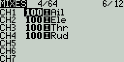
Экран Миксы
На экране Миксы (Mixes) находится список всех настроенных Миксов. Каждая строка представляет собой линию микширования и содержит следующую информацию слева направо: канал радиоуправления, вес (расход), используемый Вход (или элемент управления), имя линии микширования и активирующий переключатель. Эти пункты описаны в разделе Страница конфигурации Микса ниже.
Выберите свободный канал и нажмите на [Ролик (Enter)] для создания нового Микса, при этом откроется страница конфигурации микса.
Выберите настроенную линию микширования и нажмите на [Ролик(Enter)] чтобы переключиться между режимами Копировать/Вставить (Copy/Paste) (линия выделена сплошной заливкой) и Переместить (Move) (линия выделена заливкой с пунктирным контуром). В режиме Copy/Paste создаётся копия линии микширования, которая может быть назначена на требуемый канал управления или добавлена к существующему Миксу. В режиме Move, выбранная линия может быть перемещена на другой канал управления или на другую позицию в рамках текущего Микса. Воспользуйтесь роликом пульта для выбора позиции на которую будет скопирована/перемещена линия микширования. Нажмите на кнопку [Return] для выхода из этого режима.
Выбор существующей линии и долгое нажатие на [Enter] откроет меню со следующими действиями:
- Изменить (Edit) - открывает Страницу конфигурации Микса для этой линии микширования.
- Вставить до (Insert before) - вставляет новую линию микширования выше выбранной, в том же Миксе.
- Вставить после (Insert after)- вставляет новую линию микширования ниже выбранной, в том же Миксе.
- Копировать (Copy) - копирует выбранную линию микширования, после чего с помощью Ролика можно выбрать позицию, на которую будет добавлена копия.
- Переместить (Move) - выбирает линию микширования для перемещения, после чего с помощью Ролика можно выбрать позицию, на которую будет перемещена линия.
- Удалить (Delete) - удаляет выбранную линию микширования.
Страница конфигурации Микса
.png)
Страница конфигурации Микса
При выборе варианта edit (редактировать) для линии микширования, открывается страница со следующими параметрами конфигурации:
- Название Mix (Mix Name) - Имя линии микширования (необязательно). До 6 символов.
- Источник (Source) - Источник входного сигнала для микширования. Помимо Входов, вы можете указать стики, потенциометры, слайдеры, триммеры, физические и логические переключатели, Выходы вертолётного микшера, значения каналов, получаемые от тренерского пульта, а также другие каналы.
- Вес(Weight)- Процентное значение величины источника, используемое в этом Миксе. Долгое нажатие Ролика на этом поле позволяет переключиться с числового значения на глобальную переменную.
- Смещение (Offset) - Значение смещения, добавляемого или вычитаемого из сигнала источника.
- Трим(Trim) - Определяет, будут ли значения триммеров включены в эту линию Микса. Чтобы тримы действительно учитывались, трим для соответствующего Входа должен быть включен также на экране Входы (Inputs).
- Кривая (Curve) - Указывает тип кривой, используемой для трансляции значений входного сигнала. См. раздел Сurve на странице Входы(Inputs), где описаны разные типы используемых кривых.
- Тумблер(Switch) - Физический переключатель, активирующий линию микширования (необязательный параметр). Если переключатель не задан - линия будет активна по умолчанию.
- Предупр (Warning) - При включении этой опции аппаратура подаёт звуковой сигнал, когда данный микс активен. Возможные варианты: OFF (выкл.) или шаблоны сигнала 1, 2, 3.
- Multiplex - Определяет, как эта линия микширования взаимодействует с другими линиями того же канала.
- Add (Добавить) — добавляет свой результат к предыдущим.
- Multiply (Умножить) — умножает результат предыдущих линий на свой выход.
- Replace (Заменить) — заменяет результат всех предыдущих линий своим значением.
- Режим(Modes) - Указывает, в каких режимах полёта активен данный микс. Активные режимы отображаются как видимые.
- Задер вверх (Delay up) - создаёт временную задержку (в секундах) между увеличением значения источника и появлением изменения на выходе.
- Задер вниз (Delay down) - создаёт задержку (в секундах) между уменьшением значения источника и отражением этого на выходе.
- Точн. замедл (Slow prec) - Задаёт точность отображения времени замедления (0.0 или 0.00).
- Замед вверх (Slow up) - регулирует скорость перехода при увеличении значения источника. Указывается время перехода от -100% до +100% в секундах (от 0.00 до 25.00 сек).
- Замедл вниз (Slow down) - регулирует скорость перехода при уменьшении значения источника. Указывается время перехода от -100% до +100% в секундах (от 0.00 до 25.00).
Нажмите на кнопку [PAGE>] для перехода на экран Выходы (Outputs).
Выходы (Outputs)
Экран Выходы (Outputs) используется для окончательной настройки данных управления — включая подтриммеры (Subtrim), кривые (Curve), конечные точки (Min/Max) и центральные значения каналов управления — перед тем, как данные будут отправлены в радиомодуль (RF-модуль). Здесь задаются: центр канала, пределы (Limits) (чтобы избежать заклинивания сервоприводов) и инвертирование управляющего сигнала (Direction).
Трим (Trim) — это временная корректировка органа управления, обычно выполняемая во время полёта с помощью триммера. Подтриммер (Subtrim) — это полупостоянная корректировка, обычно задаваемая при настройке модели в параметрах выходов.
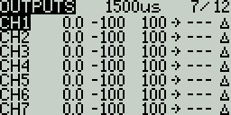
Экран Выходы (Outputs)
Экран Выходов отображает все выходные каналы. Для каждой строки выходного канала показываются значения подтриммера (Subtrim), минимального и максимального предела (Min/Max), направления (Direction), кривой (Curve) и режима подтриммера (Subtrim Mode). Внизу списка находится опция Тримы => Подтриммеры (Trims => Subtrims) — при её выборе текущие значения триммеров добавляются к значениям подтриммеров для всех настроенных выходов, после чего тримы сбрасываются в ноль.
Выбор выходной линии и нажатие на [Enter] (Ролик) откроет меню со следующими действиями:
- Изменить (Edit) — открывает страницу конфигурации выходного канала.
- Сброс (Reset) — сбрасывает значение подтриммера в ноль (трим не изменяется).
- Копир. трим→подтримм (Cpy Trims→Subtrim) — добавляет текущее значение триммера к подтриммеру (трим не изменяется).
- Копир. стики→подтримм (Cpy Sticks→Subtrim) — добавляет текущее отклонение стика как значение подтриммера.
- Копир. мин/макс всем (Cpy min/max→all) — копирует параметры Min/Max выбранного канала во все остальные каналы.
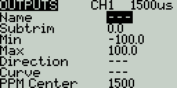
Страница конфигурации Выхода
Экран конфигурации Выхода содержит следующие параметры:
- Имя (Name) — имя выходного канала (до 6 символов).
- Подтриммер (Subtrim) — значение подтриммера (макс. 100). Долгое нажатие кнопки [ENTER] позволяет переключиться в режим Глобальной переменной (GV Mode) и выбрать соответствующую глобальную переменную.
- Мин (Min) — минимальное значение выхода. Обычно используется для предотвращения упора или заклинивания сервопривода на моделях, использующих сервоприводы для управления рулевыми поверхностями.
- Макс (Max) — максимальное значение выхода. Аналогично, предотвращает выход отклонения сервопривода за механические пределы.
- Направление (Direction) — выберите --- для нормального направления, INV — чтобы инвертировать1 выход.
- Кривая (Curve) — указывает пользовательскую кривую, применяемую к данному выходу. Подробнее см. раздел Кривые (Curves).
- PPM Центр (PPM Center) — задаёт значение ширины импульса для центрального положения выходного канала (в диапазоне 1000–2000 мс). Изменение этого параметра смещает весь диапазон сигнала, включая верхний и нижний пределы.
- Режим подтриммера (Subtrim mode) — определяет, как подтриммер влияет на пределы Min/Max:
- △ (Только центр/Center Only) - смещается только центральная точка, пределы остаются прежними. Отклик стика отличается в верхней и нижней половине хода.
- = Симметрично (Symmetrical) - верхний и нижний пределы смещаются на то же значение что и центральная точка. Отклик стика одинаков по обе стороны от средней точки.
Нажатие кнопки [PAGE>] откроет экран Кривые (Curves).
Инверсия выхода — изменение полярности управляющего сигнала, при котором направление движения сервопривода становится противоположным исходному. Используется для коррекции направления отклонения органа управления при обратной установке сервопривода или ином изменении кинематики привода. Когда инверсия выхода включена, при движении стика от минимального к максимальному положению значение управляющего сигнала (ШИМ, PPM и др.) изменяется в обратном направлении — от максимального к минимальному.
Curves
The Curves screen allows you to define custom curves to use in the Inputs, Mixes, or Output screens. The curves screen will show the configured custom curves, with a graphical representation of each curve.
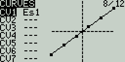
Curves Screen
Selecting one of the curves or empty curve slots will open the configuration page for that curve.
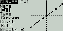
Curves Configuration Screen
Curves Configuration
The curve configuration screen has the following configurable options:
- Name - Name for the curve. Only 3 characters are possible.
- Type - Type of curve: Options are Standard and Custom
- Standard - Horizontal axis points are fixed values based on the number of points. Vertical axis points are adjustable.
- Custom - Both horizontal and vertical axes are adjustable.
- Count - number of points in the curve. Press the [Enter] button to modify the number of points. Long-pressing the [Enter] button will give the following additional options:
- Preset - Allows you to set the curve to one of the preset slope values (-45 to 45 degrees in 15 degree increments). The curve will have 5 points, and smoothing is not enabled by default.
- Mirror - Mirrors the selected curve.
- Clear - Clears all curve values from the selected curve.
- Smooth - When enabled, connects the points with curved lines instead of straight lines.
Editing Curve Points
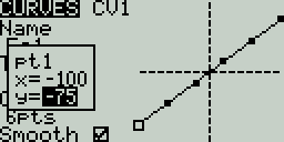
Editing Curve Points pop-up
After the last configuration option (Smooth), you will automatically begin to scroll through the configured points on the curve. To change the values of the points, press the [Enter] button and then adjust the values as desired. For Standard curves, you will only be able to adjust the Y value. For Custom curves, you can adjust both the X and Y values.
Pressing the [PAGE>] button will take you to the Logical Switches screen.
Logical Switches
Logical Switches are virtual two-position switches whose values (ON/OFF or +100/-100) are based on the evaluation (true/false) of a defined logical expression. Once configured, logical switches can be used anywhere in EdgeTX that a physical switch can be defined.
The Logical Switches page shows you all the configured logical switches as well as an overview of their configured options.
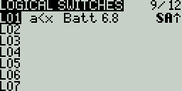
Logical Switches Screen
Selecting a logic switch will give you the following options:
- Edit - Opens the Logical Switches configuration page for the selected logical switch.
- Copy - Copies the selected logical switch
- Paste - Pastes a copied logical switch onto the selected logical switch. Note: it will overwrite the selected logical switch.
- Clear - Deletes all configuration options for the selected logical switch.
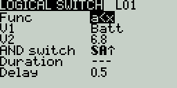
Logical Switches Configuration Screen
After selecting to edit a logical switch, you will have the following configuration options:
- Func - The logical function that you want to use. See Logical Switch Functions below for a description of the possible functions you can use.
- V1 - The first variable in the expression to evaluate.
- V2 -The second variable in the expression to evaluate.
- AND switch - Switch that must be active to allow the logical switch to be evaluated for activation.
- Duration - The duration that the logical switch will remain active (true) once meeting activation criteria.
- Delay - Delay between when the activation criteria for the logical switch has been met and when the logical switch changes to the activated state (true).
Logical Switch Functions
In the expression, a and b represent sources (sticks, switches, etc.), and x represents the constants (values) to be compared.
| Expression | Description |
|---|---|
| a=x | True when the source V1 is exactly the same as the constant V2. |
| a~x | True when the source V1 is about the same as the constant V2. |
| a>x | True when the source V1 is greater than the constant V2. |
| a<x | True when the source V1 is less than the constant V2. |
| |a|>x | True when the absolute value of the source V1 is greater than the constant V2. |
| |a|<x | True when the absolute value of the source V1 is less than the constant V2. |
| AND | True when both sources V1 and V2 are TRUE. |
| OR | True when either source V1 or V2 is TRUE. |
| XOR | True when the source V1 and V2 positions do not match. |
| Edge | Momentarily true when the source V1 has been active for the defined period of time and then deactivated. The first time field (T1) under V1 is the minimum active duration required for source V1 to activate the logical switch. The second time (T2) is the maximum time allowed for the source V1 to be active for the logic switch to be activated. When T2 is set to --, the logical switch will be true regardless of how long V1 has been active. When T2 is set to 3, if V1 is active for more than 3 seconds, the logical switch will not be set to true when the source is deactivated. When T2 is set to <<, the logical switch will be true when the time conditions in T1 are met without source V1 being deactivated. |
| a=b | True when source V1 is the same as source V2. |
| a>b | True if source V1 is greater than source V2. |
| a<b | True if source V1 is less than source V2. |
| △>x | Momentarily true every time the source V1 changes by more than the amount indicated by the constant V2. |
| |△|>x | Momentarily true every time the absolute value of the source V1 changes by more than the amount indicated by the constant V2. |
| Tim (Timer) | Momentarily true every xxx seconds. Argument V1 is the duration that the logical switch is true (active). Argument V2 is the time between logical switch activations. Repeats timer cycle as long as the defined switch is active. |
| Stky (Sticky) | "Sticks" true after switch V1 is active (true) and stays active (true) regardless of V1 position until switch V2 is activated (true) and "unsticks" or deactivates (false) the logical switch. |
Pressing the [PAGE>] button will take you to the Special Functions screen.
Special Functions
The Special Functions section is where you can configure the special functions that are included in EdgeTX. These special functions add additional functionality beyond normal model controls, such as enabling trainer mode, playing a sound, adjusting the radio backlight, adjusting radio volume, etc. On the special functions screen, you will see all configured special functions as well as some of the configured options such as function name, activation switch, if the function is enabled, and other configuration options.
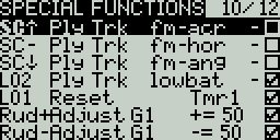
Special Functions
Configuring Special Functions
To configure a special function, select the desired special function row and press the [Enter] button. Then, scroll with the [Roller] to select the attribute that you want to edit (it will be highlighted) and press the [Enter] button to edit it (it will now be blinking). Edit the option by scrolling with the [Roller] and pressing the [Enter] button to select the desired option. Once all the options are configured, press the [Return] button to exit out of editing mode for the special function.
All special functions have the configuration options below. Additional options may be added based on the selected function. See the Functions section below for these additional options.
- Trigger - The switch or trigger that will make the special function active. Long pressing on this section will allow you to quickly select the category of the switch and filter the results. You can select the following filters: Switches, Trims, Logical Switches, Other and Invert
- Function - The function that will be used. See below for function descriptions.
- Enable - Toggle on/off to enable the function. To be able to activate the special function by a switch, it must be enabled. This option is usually the last option listed as a checkbox on the far right of the screen. Disabled special functions will not function regardless of the configured switch position.
Functions
Below are all the available functions in EdgeTX, what they do, as well as what additional configuration options that will be shown when the function is selected.
Override (Channel Override) - Overrides the defined channel with the defined value.
- CH - Channel to be overridden
- Value - Value to replace the normal channel value. (Range -100 to +100)
Trainer - Enables trainer mode.
- Value - Specifies which controls will be given over to the student. Options include Sticks (all sticks), Rud (Rudder), Ele (Elevator), Thr (Throttle), Ail (Aileron), and Chans (all channels).
Inst. Trim (Instant Trim)- Sets all trims to the current values of their respective sticks.
Reset (Reset Timer)- Resets the timer or telemetry specified in the value back to their initial values.
- Reset - Options are Tmr 1, Tmr 2, Tmr 3, All, and Telemetry. See Reset Telemetry for more information on what data is reset for each option.
Set (Set Timer) - Sets the specified timer to the specified value.
- Timer - Options are Tmr 1, Tmr 2, Tmr 3
- Value - The range is 00:00:00 to 08:59:59
Adjust (Adjust Global Variable) - Changes the value of the specified global variable.
- Global var - Select the global variable that you want to adjust.
- Mode - Select the mode to change the global variable. Options are: Constant, Mixer Source, Global var, Inc/Decrement. Long-press the [Enter] button to select the mode.
- Constant - Sets the specified global variable to the defined constant value.
- Mixer Source - Sets the specified global variable to the defined mixer source value.
- Global Var - Sets the specified global variable to the defined global variable value.
- Inc/Decrement - Increments/decrements the specified global variable by the specified amount.
Volume - Changes the radio volume. The change source is specified in the Volume dropdown.
SetFailsafe - Sets the custom failsafe values for the selected module (Internal/External) to the current stick position when activated. For this option to work, the Failsafe mode for the RF module must be set to custom.
Play Sound - Plays the sound selected in the value field when activated.
- Value - Sound to play. Possible values are Beep1/2/3, Warn1/2, Cheep, Ratata, Tick, Siren, Ring, SciFi, Robot, Chirp, Tada, Crickt, AlmClk. Note: SD card sound pack is not required.
- Repeat - Frequency to repeat the sound. Options are !1x (do not play at startup even if the switch is active), 1x (play once), 1s thru 60s (play every xx seconds).
Play Track - Plays the .wav sound file selected in the value field when activated.
- Value - .wav sound file to play from the SD card.
- Repeat - Frequency to repeat the track. Options are !1x (do not play at startup even if the switch is active), 1x (play once), 1s thru 60s (play every xx seconds).
Play Val - Announces the value of the selected element in the value field.
- Value - The source for the value to announce. It can be an input, stick, pot, slider, trim, physical and logical switch, trainer import channel value, global variable, telemetry sensor or channel.
- Repeat - Frequency to repeat the announcement. Options are !1x (do not announce at startup even if the switch is active), 1x (announce once), 1s thru 60s (announce every xx seconds).
Lua Script - Executes the Lua script defined in the value field. The Lua script must be located in /SCRIPTS/FUNCTIONS/ folder on the SD card. Lua scripts that display information on the screen cannot be executed with this special function.
- Value - LUA script file to play from the SD card.
- Repeat - Frequency to repeat the Lua script. Options are: ON (repeat indefinately as long as switch is active) or 1x (once)
BgMusic - Plays the .wav file selected in the value field on a loop when enabled. The file shall be in the SOUNDS/(language)/ folder on the SD card.
BgMusic II - Temporarily pauses the .wav file playback specified in the BgMusic
Vario - Enables the variometer beeping sound for the ascent and descent of the model.
Haptic - Causes the radio to vibrate (haptic feedback) when enabled.
- Value - Type of vibration pattern. Options are: 0 - 4.
- Repeat - Frequency to repeat the vibration pattern. Options are !1x (do not vibrate at startup even if the switch is active), 1x (vibrate once), 1s thru 60s (vibrate every xx seconds).
SD Logs - Creates a log .csv file of the radio and telemetry values in the LOGS folder on the SD Card. The radio will create a new entry into the log file based on the frequency configured in the Value setting. The value options are 0.0s - 25.5s (Note: 0.0 effectively disables this option). Each time the function is activated, the radio will create a new log file provided that the function is activated at least as long as the value setting. Note: Logging will not start if SD card has less than 50mb of free space.
Backlight - adjusts the screen contrast (LED screens) or OLED brightness (OLED screens) based on the source defined in the value dropdown.
Screenshot - Creates screenshot as a .bmp file in the SCREENSHOT folder on the SD Card.
RacingMode - Enables racing mode (low latency) for FrSky Archer RS receivers. Racing mode must also be enabled in External RF Module Settings.
Audio Amp Off (select radios) - Disables the Audio Amplifier so that no sound comes from the speaker, including annoying feedback or interferance. This option is only available on select radios.
RGB Led - Executes the selected LED related Lua script on the SD card in the Scripts -> RGBLED folder.
Pressing the [PAGE>] button will take you to the Telemetry screen.
Telemetry
Telemetry is data received from the model to the radio from various sensors. These sensors may be included in the radio receiver or flight controller or may be separate sensors, such as GPS, variometer, or magnetometer. The received telemerty data can be displayed by EdgeTX in widgets, configured in alarms or audio call-outs.
The Telemetry screen is where you configure these sensors to use in EdgeTX. Below are the following configuration options:
Sensors
.png)
Sensors portion of the Telemetry screen
All previously configured sensors are listed here. The list is collapsible by clicking on the arrow icon to the right side of the Sensors label. The number of configured sensors will be displayed in parentheses, ex: (6), when the sensor list is collapsed. Sensors that have not received data since the model was loaded or the telemetry values were reset display --- for the values. The asterisk * to the left of the sensor value will flash when the sensor has received a data update. A solid asterisk***** indicates that the sensors that are receiving regular updates. Sensors that are no longer receiving regular updates will not be marked with the asterisk*****. See Common Telemetry Sensors for a list of commonly used sensors in EdgeTX.
The following options are listed under the sensor list.
- Discover New: When selected, it will look for new sensors on the model and automatically configure them. If the sensor list is collapsed when a new sensor is discovered, the newly found sensor will be visible on the sensor list (old sensors will remain collapesd/hidden).
- Add New: When selected, it will create a new blank sensor for that must be configured manually.
- Delete All: This option will delete all previously configured sensors.
- No inst. (ignore instances): This option prevents multiple sensors from reporting the same telemetry data.
If you long-press the [Enter] button for a specific sensor, the following options will be displayed:
- Edit: Allows you to edit the sensor's configuration options.
- Copy: Creates a copy of that sensor.
- Delete: Deletes that sensor.
See the Sensor Configuration page for a detailed description of all the configuration options for setting up or editing sensors.
RX Status
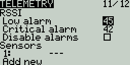
RSSI Portion of Telemetry screen
Here you can configure the threshold for the RX alarms. The Rx-Stats label will change (Rx-Stats, RSSI, Rqly, Sgnl) depending on the protocol that is used with the model.
- Low alarm - The threshold value when the "RF signal low" voice prompt will be played. The recommended value is 45.
- Critical alarm - The threshold value when the "RF signal critical" voice prompt will be played. The recommended value is 42.
- Disable telemetry alarms - When enabled, no alarm voice prompts will be played.
Variometer
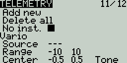
A variometer detects changes in the model altitude. EdgeTX can alert the user of these altitude changes by providing a rising/lower pitched tone. Use the Variometer menu on the Radio Setup page to set the actual frequency and volume of the tone to be played. The following options exist to configure the variometer alarm.
- Source - Specifies the sensor to use as the variometer. It is selected from the telemetry sensors added in Sensors section.
- Range - Specifies the ascent/descent range that will trigger the change in the Variometer beeping pitch. If climb/descent rate is within the range specified here, beeping pitch will change according to that value. When it goes beyond the range specified here, beeping pitch will stop changing. Units are meters/second or feet/second based on the Units setting on the Radio Setup page.
- Center - Specify the range for ignoring changes in climb/descent rates. When the climb/descent rate is within the range specified here, the beeping pitch will not change.
- Tone/Silent - Specifies whether to beep when climb/descent rate is within the range specified by Center.
Pressing the [PAGE>] button will take you to the Display screen.
Sensor Configuration
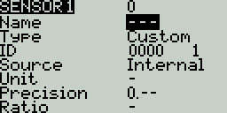
Sensor Configuration page
The below options can be configured for sensors:
- Name: Name of the sensor - up to 4 characters.
- Type: Options are custom or calculated. Custom sensors are defined by the hardware. Calculated sensors are a sensors whose value is calculated using other sensors values. See below for more information on calculated sensors.
- ID: This number indicates what type of sensore it is. It contains two parts. The first part is the ID number which defines the sensor type. The second part is the instance number for the hardware. If multiple sensors of the same type are configures, the instance numbers must be unique.
- Unit: The unit for the sensor. This unit is used when the sensor value is displayed on the screen or read aloud.
- Precison: Specifies the number of digits after the decimal point when the sensor value is displayed on the screen. The number is truncated based on this setting.
- Ratio: Specifies the ratio value to multiply with the sensor value as needed by some sensors.
- Offset: Specifies the offset value to add to the sensor value.
- Auto Offset: When selected, the first received value is used as offset. You can use the Reset telemetry option to reset the offset on already configured sensors.
- Positive: When selected, the value of the sensor will be displayed only when it is a positive number. Displays zero when the sensor value becomes a negative number.
- Filter: When selected, the sensor value becomes a rolling average of the last 5 received values.
- Logs: When selected, the value of this sensor will be saved in the log file. SD Card logging is configured in Special Functions or Global Functions.
Calculated sensors contain the additional configuration options:
- Formula: Type of calculation to use. Options include:
- Add: Add the values of up to 4 designated sensors.
- Average: Calculates the average value of up to four designated sensors.
- Minimum: Find the minimum value of up to 4 designated sensors.
- Maximum: Find the maximum value of up to 4 designated sensors.
- Multiply: Multiplies the value of 2 sensors.
- Totalize: Calculate the cumulative value of one sensor.
- Cell: This is the formula for FrSKY Lipo battery sensor. It displays cell voltage specified by the number in "Cell index" field.
If you specify "Lowest" in "Cell index" field, the voltage of the cell with the lowest is displayed.
If you specify "Highest" in "Cell index" field, the voltage of the cell with the highest is displayed.
If you specify "Delta" in "Cell index" field, the voltage difference between lowest and highest cell is displayed - Consumpt: Calculates the power consumption (mAh) by cumulatively add the values of current sensor.
- Distance: Calculates the distance between the receiver and the radio using GPS sensor and altimeter values.
- Source 1, 2, 3, 4: The sensors that will provide the argument values that are used in the formula defined above.
- Persistent: When selected the sensor values will be saved when switching between models or powering down the radio.
Common Telemetry Sensors
The following sensors are commonly used and normal automatically detected by EdgeTX:
| Name | Description | Data source |
|---|---|---|
| 1RSS | Received signal strength antenna 1 (RSSI) | Receiver |
| 2RSS | Received signal strength antenna 2 (RSSI) | Receiver |
| Rqly | Receiver link quality (valid packets) | Receiver |
| RSNR | Receiver signal-to-noise ratio | Receiver |
| RFMD | Receiver packet rate | Receiver |
| TPWR | Transmitter transmitting power | Transmitter |
| TRSS | Transmitter signal strength antenna | Transmitter |
| TQly | Transmitter link quality (valid packets) | Transmitter |
| TSNR | Transmitter signal-to-noise ratio | Transmitter |
| ANT | Sensor for debugging only | Transmitter |
| GPS | GPS Coordinates | GPS / Flight Controller |
| Alt | GPS Altitudes | GPS / Flight Controller |
| Sats | GPS Satellites acquired | GPS / Flight Controller |
| Hdg | Magnetic orientation | GPS / Flight Controller |
| RXBt | Battery voltage | Flight Controller |
| Curr | Current draw | Flight Controller |
| Capa | Current consumption | Flight Controller |
| Ptch | FC Pitch angle | Flight Controller |
| Roll | FC Roll angle | Flight Controller |
| Yaw | FC Yaw angle | Flight Controller |
| FM | Flight mode | Flight Controller |
| VSPD | Vertical Speed | Flight Controller w/ Baro |
Display
The Display screen is where you configure the telemetry screens shown when pressing the [Tele] button from the main screen.
You can configure up to Four telemetry screens. You can choose one of the following display types for each screen:
Nums (Numbers) - The numbers type displays the number value of the selected telemetry sensor or other configured object. The screen will be divided into two columns with four rows - each cell can display the data from a different sensor or object. On the display screen, the top bar will show the model name, radio battery voltage, and time in addition to the configured cells. If Timer1 is configured in the model, then it will replace the model name in the top bar.
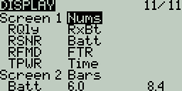
Display Numbers Configuration
.png)
Display Screen with Numbers
Bars - The Bars type displays a bar graph representing the value of the selected telemetry sensor or other configured object. The screen will be divided into four rows - each row can display the data from a different sensor or object. For each sensor, you must define the minimum and maximum values for the bars. On the display screen, the top bar will show the model name, radio battery voltage, and time in addition to the configured cells. If Timer1 is configured in the model, then it will replace the model name in the top bar. Additionally, a 5th bar will be shown at the bottom with the RSSI value.
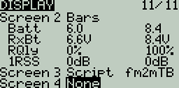
Display Bars Configuration
.png)
Display Screen with Bars
Script- The Script type executes the telemetry Lua script that is configured. The telemetry Lua script must be located in the SD card folder: SD Card->Scripts->Telemetry in order to be available to be configured.
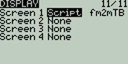
Display Script Configuration
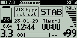
Display Screen with fm2m Lua Script
To configure the screens, scroll to the screen you want to configure and then press the [Enter] button. Then scroll to select the type of screen that you want to use and press the [Enter] button to select it. Depending on the selected screen type, you can then configure the telemetry objects for each cell by scrolling to the desired object and selecting it by pressing the [Enter] button. After all desired cells are configured, press the [Return] button to exit out of the configuration menu.
Radio Settings
Tools
Pressing the [SYS] button from the Main view will open the Tools screen.
The Tools page in Radio Settings is where you can select Lua script-based tools for execution. Lua scripts that are located on the SD card in the Tools folder will be listed here. Selecting a tool will execute it. By default, EdgeTX includes several tools. Other tools can be downloaded and added to the SD card as well. The following tools are included in the default EdgeTX SD card.
Wizard Loader
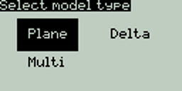
Setup Wizard
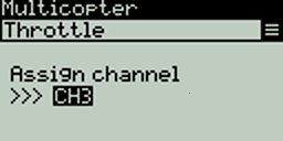
Setup Wizard Configuration menu
The Wizard Loader tool assists you in setting up a new model by running a setup wizard for a particular model type. Once the model type is selected, the wizard will take you through a series of prompts and then configure your selected model based on the information provided.
NOTE: The wizard does not create a new model, it only configures the currently selected model. You must manually create a new model first and then run the wizard. If you run this wizard on an already configured model, it will overwrite your model settings!
Pressing the [PAGE>] button will take you to the SD Card screen.
SD Card
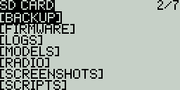
SD Card Screen
The SD Card screen shows you the contents of your SD card, allows you to navigate the folders and interact with the files in the folders. All folders contain a README.txt file that describes what type of files belong in this folder. After selecting a file in one of the folders, you will be presented with some of the options below, depending on the file type that was selected:
- Assign bitmap - Assigns the selected image file as the model image of the currently selected model.
- Copy - Copies the selected file.
- Delete - Deletes the selected file.
- Execute - Executes a Lua script. Used for files ending in .lua
- Flash [target]- Flashes the selected firmware file to the select target module. Examples: Flash Bootloader, Flast Internal Multi.
- Paste - Pastes the copied file.
- Play - Plays the selected sound file.
- Rename - Renames the file.
- View text - Views the selected .txt, .csv, and .lua files.
The folders listed on the SD card screen are the same as what you will see when connecting your radio to your computer. Below are the folder names and explanations for all the folders that come with the default EdgeTX SD Card.
BACKUP
The backup folder contains model files for models that were backed up from the EEPROM. This folder will only be present on radios that store the model files in EEPROM.
FIRMWARE
Place the firmware files that you want to flash in this folder. This folder is empty by default (except for the readme.txt file). When selecting a .bin file you will be given the option to flash the firmware to a particular module. Also, only firmware files in this location will be visible from the bootloader menu.
IMAGES
NOTE: This folder is only used for radios with 212x64 displays.
Place your custom model image files in this folder. This folder is empty by default (except for the readme.txt file). Selecting an image file will give you the option to Assign Bitmap, which assigns the selected image file as the model image of the currently selected model.
The ideal image size for model images is 64x32 pixels. The picture format should be .bmp The image file name should not exceed 9 characters and the image formatting should be 4 bit indexed colored mode.
LOGS
This is where the log files that are configured in the special function SD Logs are written. These files can be viewed with the View text option. This folder is empty by default (except for the readme.txt file).
MODELS
This is where the model files, label information, and preflight checklists are stored. Each model will have a model[#].yml file that contains all configured options.
Models that are deleted via the radio will be moved to the DELETED folder that is included in this folder. The remaining model files are what will be visible on the Model Select screen.
If you have configured the Display checklist option in model settings, the model notes file goes in this folder. The model notes file must be a .txt file and must have the EXACT same name as the model it is for, for example: Mobula6.txt. The text in the file is up to the user.
RADIO
This folder contains the radio.yml file. This file contains all the radio configuration data. If this file is corrupted or missing, the radio will go into Emergency Mode and will create a new radio.yml file with the default settings.
SCREENSHOTS
This is where the screenshot image files that are configured in the special function Screenshot are written. This folder is empty by default (except for the readme.txt file).
SCRIPTS
This folder and its subfolders are where the Lua scripts get placed. It contains the following sub-folders by default. You can download additional Lua scripts from https://github.com/EdgeTX/lua-scripts.
- Functions - This folder is where the functions Lua scripts that can be activated by the special function Lua Script must be placed. This folder is empty by default (except for the readme.txt file). More information about function Lua scripts can be found here: Function Scripts.
- Mixes - This folder is where the Lua mixer scripts shall be placed. This folder is empty by default (except for the readme.txt file). More information about Mixer Lua scripts can be found here: Custom Mixer Scripts
- RGBLED - This folder is where Lua scripts that control the RGB Leds (if hardware available) are stored.
- Tools - Contains the Lua scripts that are available in the Tools screen.
- Wizards - Contains the Wizard Lua scripts that are available in the Tools screen.
SOUNDS
This folder is where the EdgeTX sound packs for your radio get placed. The sound packs are language-specific and correlate to the Voice language option in Radio Setup. Selecting a sound file from this folder will give you the option Play, which plays the selected sound file.
Sound packs are available for manual download at: https://github.com/EdgeTX/edgetx-sdcard-sounds/releases. It is also possible to create custom sounds to use in EdgeTX. For your custom sounds to be playable by EdgeTX ensure that they meet the following criteria:
- File Name: 123456.wav (up to 6 characters plus .wav)
- Sample Rate: 32 kHz (or 16 Khz, 8Khz)
- Bits / Sample: 16 (or 8)
- Tracks: 1, mono
- Compression Codec: PCM
Pressing the [PAGE>] button will take you to the Radio Setup screen.
Radio Setup

Radio Setup
The Radio Setup screen is where you configure basic settings for your radio. It contains the following options:
Date - The current date. This date is used for the SD card log files.
Time - The current time. This time is used for the SD card log files.
Batt. range - Sets the maximum and minimum voltage for the battery meter. This should be set based on the type of battery you are using.
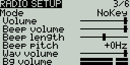
Sound Settings
Sound
Mode - configures when to play sounds.
- All - Beeps when the buttons are pressed and sounds are played when there are alerts or warnings.
- No Key - No beeps when buttons are pressed or the scroll wheel is turned but does play sounds when there are alerts or warnings. Also plays sounds triggered by special functions.
- Alarm - Only plays alarm or warning sounds. Also plays sounds triggered by special functions.
- Quiet - No Beeps or sounds are played.
Volume - The master volume for the radio.
Beep Volume - Self-explanatory
Beep Length - Self-explanatory
Beep Pitch - Self-explanatory
Wav volume - The volume for alerts and warnings and sounds that are played with the Play track special function
Bg volume - The volume for background .wav files (music) that are played with the BGMusic special function
.png)
Variometer Settings
Vario (Variometer)
Volume - Volume for variometer beeps
Pitch zero - Low pitch frequency
Pitch max - High pitch frequency
Repeat Zero - The time before the tone repeats in milliseconds
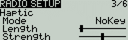
Haptic Settings
Haptic
Mode - configures when the radio vibrates.
- All - Vibrates when the buttons are pressed and when there are alerts or warnings.
- No Key - No vibrations when buttons are the pressed or scroll wheel is turned but does vibrate when there are alerts or warnings.
- Alarm - Only vibrates for alarms or warning sounds.
- Quiet - No vibrations are made
Length - Duration of vibration.
Strength - Strength of vibration
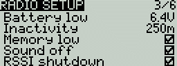
Alarms Settings
Alarms
Battery Low - Voltage to trigger low battery alarm.
Inactivity - Time to trigger inactivity warning.
Memory low - Enable/disable low memory warning.
Sound Off - An "alarms disabled" visual warning is displayed when the transmitter is turned on if the sound mode is set to quiet.
RSSI Shutdown - Checks if a receiver is still connected to the radio on attempted shutdown. Makes a audio and visual alert if one is detected.
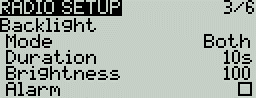
Backlight Settings
Backlight
Mode
- Off – Always off.
- Keys – Turns on when buttons are pressed.
- Ctrl – Turns on when sticks, switches, and knobs are used.
- Both – Turns on when buttons, sticks, switches, and knobs are used.
- ON – Always on.
Duration - The length in seconds that the backlight is on. The minimum value is 5 seconds. The maximum value is 600 seconds.
Brightness - Adjusts the screen backlight brightness level.
Alarm - The backlight turns on when there are alarms or warnings.
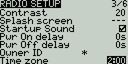
Contrast - For LCD displays, adjusts the screen contrast setting. For OLED displays. adjusts the OLED brightness level.
Splash Screen - Duration to display the splash screen.
Startup Sound - Toggles whether to enable/disable startup sound.
Power On delay - The delay between when the power button is pushed and when the radio turns on. The options are: 0s, 1s, 2s, 3s
Pwr Off delay - The delay between when the power button is pushed and when the radio shuts off. The options are: 0s, 1s, 2s, 3s, 4s. It is recommended to set at least a 1s delay in order to prevent the radio from being shut off in the case of an accidental button press.
Owner ID - Custom registration ID used only for users with ISRM modules.
Time Zone - The time offset from UTC where the radio is being used. Can be configured in 15 minute increments.
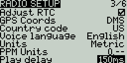
Adjust RTC - Adjust the transmitter's real-time clock to match the time determined by the GPS.
GPS Coords - The GPS coordinate format that will be displayed.
Country code - Used by some RF modules to ensure adherence to local regulatory RF requirements. Options are America, Japan, Europe.
Voice language - Language for the voice pack. This setting and the voice pack folder on the SD card must match for the sounds to be played.
Units - Units of measure. Options are metric or imperial.
PPM Units - Level of accuracy for PPM values are displyed. Options are 0.- or 0.0
Play delay (sw. mid pos) - The minimum time in milliseconds a switch must be in the middle position before a special function will get activated. This is used to prevent the middle position from being activated on a three-position switch when switching from low position to high position.
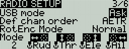
USB Mode - Sets the default action when a USB cable is plugged into the USB data port and the radio is powered on. Options are: Ask, Joystick, Storage, and Serial.
Def Chan Ord - The default channel order for new models and the trainer screen. The letters stand for: A = Aileron, E = Elevator, T = Throttle, R = Rudder. Changing this setting does not affect existing models. On Surface Radios, the letters stand for S=Steering, T=Throttle.
RotEnc Mode (Rotary Encoder Mode) - Sets the direction of the rotary encode for the Roller. The options are:
- Normal (default)
- Inverted = Reverses the direction of the roller
- V-I H-N = Vertical Inverted, Horizontal Normal
- V-I H-A = Vertical Inverted, Horizontal Alternate (Inverted)
- V-N E-I = Vertical Normal, Edit Inverted (inverted when editing text)
Mode - The stick mode that will be used for the transmitter. Defined by what actions the left stick takes. The options are:
| Option | Left stick H | Left stick V | Right stick H | Right stick V |
|---|---|---|---|---|
| 1: Left = Rud+Ele | Rudder (Yaw) | Elevator (Pitch) | Aileron (Roll) | Throttle |
| 2: Left = Rud+Thr | Rudder (Yaw) | Throttle | Aileron (Roll) | Elevator (Pitch) |
| 3: Left = Ail+Ele | Aileron (Roll) | Elevator (Pitch) | Rudder (Yaw) | Throttle |
| 4: Left = Ail+Thr | Aileron (Roll) | Throttle | Rudder (Yaw) | Elevator (Pitch) |
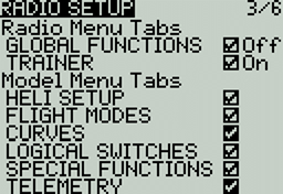
Enabled Features
Enabled Features
The Enabled Features section of Radio Setup allows you to configure the Global settings for which tabs are visible in the Radio Setup and Model Settings area of EdgeTX. The configuration setting for the active model will show to the right of the checkbox. The model configuration will override the global configuration.
EXCEPTION: Turning off the Global / Special Functions tab will disable configured global / special functions for that model.
Pressing the [PAGE>] button will take you to the Global Functions screen.
Global Functions
Global functions are special functions that apply to all models on the Radio. They are configured exactly as model Special Functions and the same functions are available. For more information about configuring Global Functions, refer to the Special Functions section as they are essentially the same.
Pressing the [PAGE>] button will take you to the Trainer screen.
Trainer
The Trainer screen in Radio Settings is used to configure how the radio in Master mode will handle the signals from the radio in Slave mode. It contains the below configuration options.

Trainer Ccreen in Radio Settings
For each of the four main control inputs (Ail, Ele, Thr, Rud), the following options can be configured (for each row, from left to right).
Mode - How the radio in Master mode will handle the signals from the radio in Slave mode.
- OFF - Stick values from the radio in Master mode will be used - no input from the radio in Slave mode.
- += Adds the stick values from both the radios in Master and Slave modes.
- := Replaces the stick values from the radio in Master mode with the stick values from the radio in Slave mode. (Default)
- Weight - Percentage of stick travel to use of the radio in Slave mode. Use negative values to change the stick direction.
- Source channel - The channel from the radio in Slave mode that is mapped the control input.
Multiplier - This value changes the weight of all the sticks together.
Cal (calibrate)- Sets the center stick value of the radio in Slave mode.
Pressing the [PAGE>] button will take you to the Hardware screen.
Hardware
The Hardware screen is where you configure hardware specific-settings for your radio. It shows all physical hardware objects (sticks, pots, switches) and allows for their modifications. It is also where you can calibrate your sticks and pots. It also contains additional configuration options.
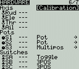
Hardware Screen
Calibration
To calibrate your physical radio controls (sticks, pots, sliders & 6-position switch), highlight the [Calibration] option and press the [Enter] button. The radio will prompt you through the calibration steps.
Inputs, Sticks, Pots, and Switches Buttons List
Selecting one of the Axis, Pots, or Switches lines from the list will allow you to add a 3 character label to the control as well as change the type of control as needed. Additionally, you can invert the direction of the Pots by selecting the ->
Additional hardware configuration options
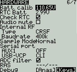
Hardware Screen
Batt. Calib (Battery Calibration) - Set this value to match the transmitter battery voltage. This ensures that the displayed battery voltage is accurate.
RTC Batt - The current voltage of the RTC battery. The RTC (real time clock) battery keeps the radio's date and time accurate even when no main radio battery is present.
Check RTC - When enabled, checks the RTC battery at startup and warns you if the battery voltage is low.
Audio Mute - When enabled, puts the transmitter in mute mode until a sound needs to be played. This prevents interference noise from high-powered TX modules from coming out of the transmitter speakers.
Internal RF Type - Select the module type for the internal module bay. Options are: Multi, XJT, ISRM, CRSF. When CRSF is selected, you can also select the baud rate. You can read more about baud rates here.
Sample Mode (External RF)- Options are Normal and OneBit. The default setting of Normal should be used by most users. Only users of X9D+ and X7 radios may want to use OneBit mode.
Bluetooth
Mode - mode that the bluetooth module will be used in. The options are:
- --- - Off
- Telemetry - used for sending telemtry data over bluetooth.
- Trainer - used for bluetooth trainer mode
One a mode is selected, you will see the following information:
- PIN Code - PIN code for bluetooth device in the radio (visible in Telemetry mode only)
- Local addr - Identifying address of the bluetooth device in the radio.
- Dist addr - Identifying address of bluetooth device that radio is connected to.
Name - the name the bluetooth device will be seen as.
Serial Port - Displays a list of available auxiliary serial ports that can be configured and used. The listed ports are based on the ports that are available in the particular radio hardware. The ports listed below are for example only and may not be present in your radio.
-
AUX1 - First available auxiliary serial port can be configured with the below options:
- OFF - Turned off.
- Telem Mirror - The same telemetry data that goes to the external module bay is sent to the serial port.
- Telemetry In - Receive telemetry data over the serial port.
- SBUS Trainer - Connect the Instructor and Student radios over the serial port.
- LUA - Send/receive data to/from Lua script.
- GPS - Receive GPS telemetry data over the serial port.
- CLI - Send commands to the radio via the command line.
-
USB-VCP - Virtual COM Port. This is one of the options presented when connecting your radio to the PC with most radios. Is often set to 'CLI' for radios with internal ExpressLRS RF modules in order to do firmware updates.
ADC Filter - Enables or disables the ADC Filter. This filter can also be enabled/disabled per model in the model settings.
RAS - (Formerly SWR) Reflected antenna signal. Lower numbers are better, with a 1:1 ratio being theoretically the best. Not supported by all RF Protocols.
Debug
The debug section allows for testing and debugging of the analog controls and keys.
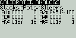
Debug Analogs screen
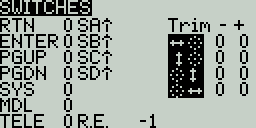
Debug Keys screen
Debug Analogs - These screens will show you the data for your analog controls (Sticks, Sliders, Pots, 6-position switch). There are two views - Calibrated Analogs, Raw Analogs (5 Hz).
Debug Keys - This screen will show you the digital data for your keys, switches, trims, and the rotary encoder (roller).
Pressing the [PAGE>] button will take you to the Version screen.
Version
Version
The Version screen displays information about the current EdgeTX version that is being used:
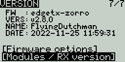
Version Screen
- FW - Firmware name
- VERS - Firmware version
- NAME: Firmware Codename
- DATE - Date & time the firmware was compiled
Firmware Options
To view the build options that were enabled when compiled, highlight the [Firmware options] options and press the [Enter] button.
Firmware Options Screen
Modules / RX Version
To view the Modules / RX Version information about the activated RX modules for the currently selected model, highlight the [Modules / RX Version] option and press the [Enter] button.

Modules / RX Version Screen
Другие переводы этого руководства
Здесь размещены ссылки на другие переводы руководства пользователя EdgeTX
Официальное руководство пользователя EdgeTX
Официальное руководство пользователя (на английском языке) поддерживается и обновляется командой EdgeTX, оно обычно содержит наиболее актуальные сведения и позволяет переключение между различными версиями документа. Найти его можно по ссылке https://manual.edgetx.org/ Там же есть ссылки на неофициальные переводы на других языках.
Перевод на русский язык от Руслана Кергет
Этот перевод был создан Русланом на основе версии 2.9 и включает в себя раздел 4 - Аппаратуры управления с цветным дисплеем
Руководство пользователя для аппаратур управления с цветным дисплеем от Руслана Кергет
На данный момент, пока полный перевод данного руководства пользователя (на основе версии 2.11) ещё не закончен, воспользуйтесь переводом Руслана для раздела 4.
Доступ в режиме загрузчика и DFU
Для низкоуровневого доступа к аппаратуре управления, в EdgeTX используется программа Загрузчик1 и режим DFU. Режим загрузчика2 и режим DFU3 включаются по-разному на разных моделях пультов управления. Ниже вы найдёте инструкции по активации этих режимов для различных моделей.
BETAFPV LiteRadio 3 Pro
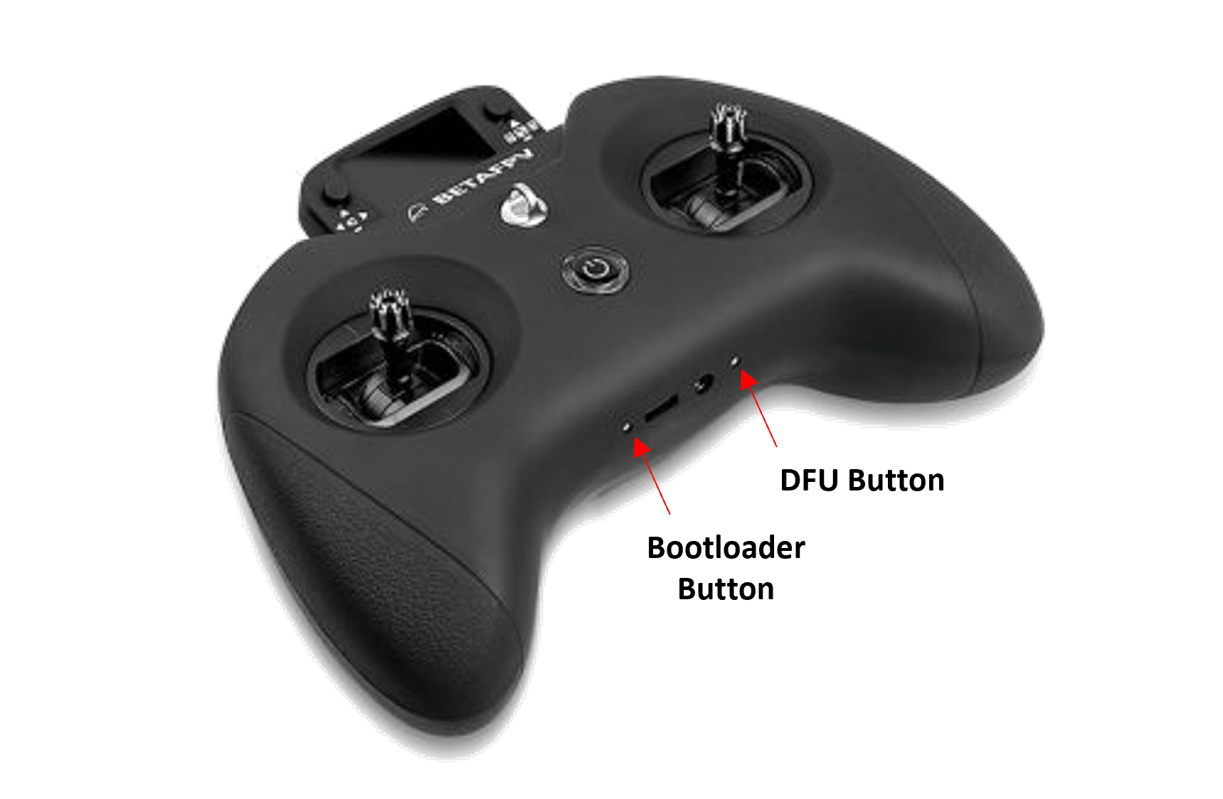
BETAFPV LiteRadio 3 Pro - кнопки режимов Загрузчика и DFU
Загрузчик: Выключите аппаратуру управления. Зажмите кнопку Загрузчика (Bootloader) и кнопку включения, затем одновременно отпустите их.
DFU: Выключите аппаратуру управления. Нажмите и удерживайте кнопку DFU, подключите USB-кабель от компьютера, отпустите кнопку DFU.
FlySky NV14 / EL18
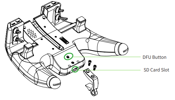
FlySky NV14/EL18 - кнопка DFU
Загрузчик: Выключите аппаратуру управления. Сведите в центр оба триммера и нажмите на обе кнопки включения.
DFU: Выключите аппаратуру управления. Нажмите и удерживайте кнопку DFU, подключите USB-кабель от компьютера, отпустите кнопку DFU.
FlySky PL18 / PL18 EV
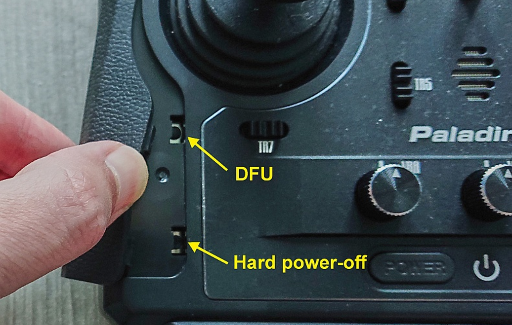
PL18 PL18 EV - кнопка DFU
Загрузчик: Выключите аппаратуру управления. Сведите к центру оба горизонтальных триммера (TR7 and TR8) и нажмите на обе кнопки включения.
DFU: Выключите аппаратуру управления. Нажмите и удерживайте кнопку DFU, подключите USB-кабель от компьютера, отпустите кнопку DFU.
iFlight Commando8
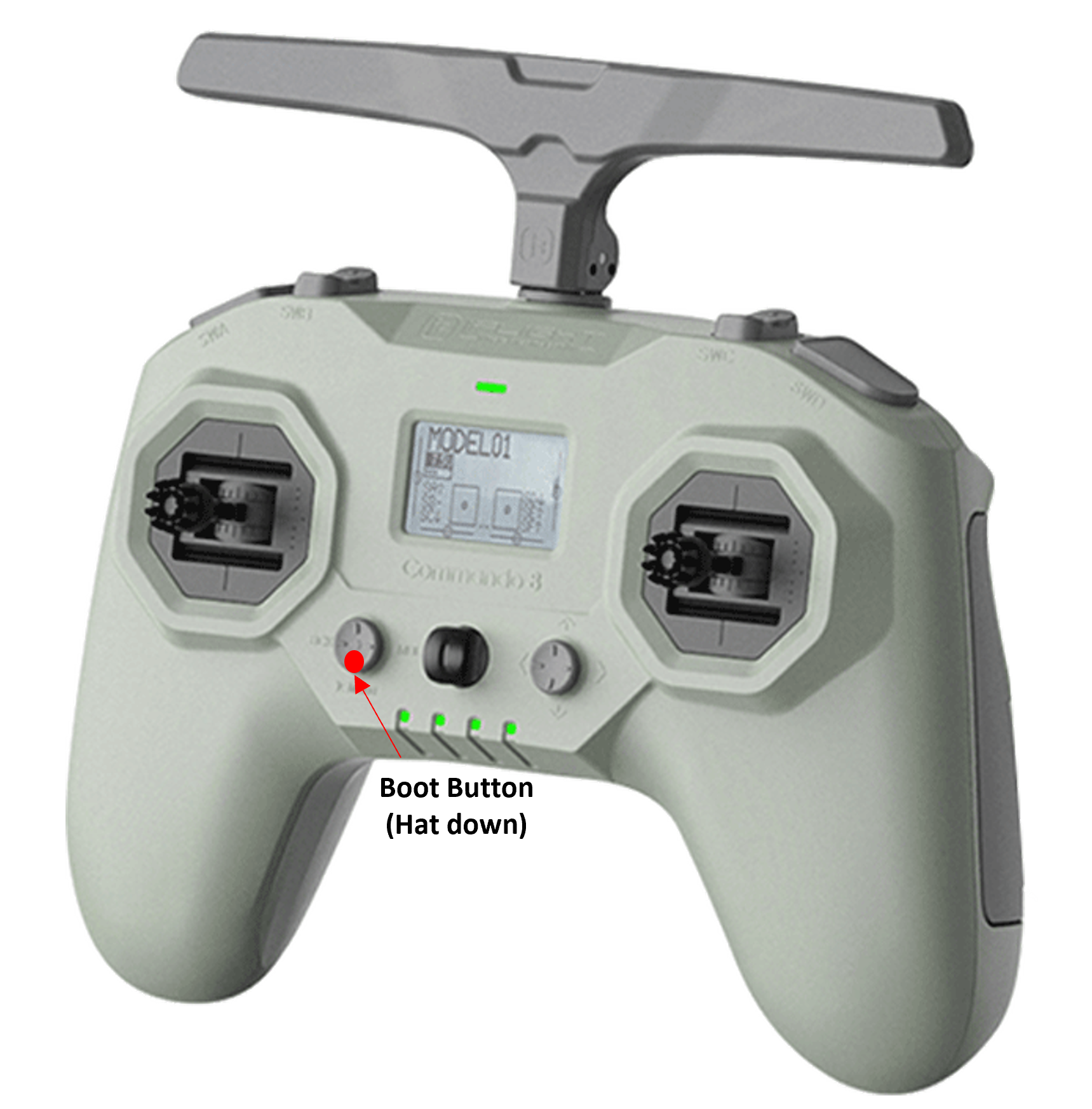
iFlight Commando8 - кнопка Boot
Загрузчик: Выключите аппаратуру управления. Зажмите кнопку Boot (левый мини-джойстик вниз) и кнопку включения, затем одновременно отпустите их.
DFU: Выключите аппаратуру управления. Подключите USB-кабель от компьютера. Зажмите кнопку Boot (левый мини-джойстик вниз), затем нажмите и удерживайте кнопку включения. Экран аппаратуры останется выключенным, светодиоды загорятся по очереди слева направо. Теперь аппаратура находится в режиме DFU.
Jumper T12/T16/T18
Загрузчик: Выключите аппаратуру управления. Сведите к центру оба горизонтальных триммера и нажмите кнопку включения аппаратуры.
DFU: Выключите аппаратуру управления. Подключите USB-кабель к верхнему USB порту аппаратуры.
Jumper T12 MAX
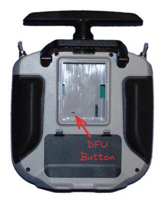
Jumper T12 MAX - кнопка DFU
Загрузчик: Выключите аппаратуру управления. Сведите к центру оба горизонтальных триммера и нажмите кнопку включения аппаратуры.
DFU: Выключите аппаратуру управления. Нажмите и удерживайте кнопку DFU, подключите USB-кабель от компьютера, отпустите кнопку DFU.
Jumper T14/T15
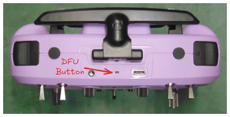
Jumper T14/T15 - кнопка DFU
Загрузчик: Выключите аппаратуру управления. Сведите к центру оба горизонтальных триммера и нажмите кнопку включения аппаратуры.
DFU: Выключите аппаратуру управления. Нажмите и удерживайте кнопку DFU, подключите USB-кабель от компьютера, отпустите кнопку DFU.
Jumper T-20/T-20S
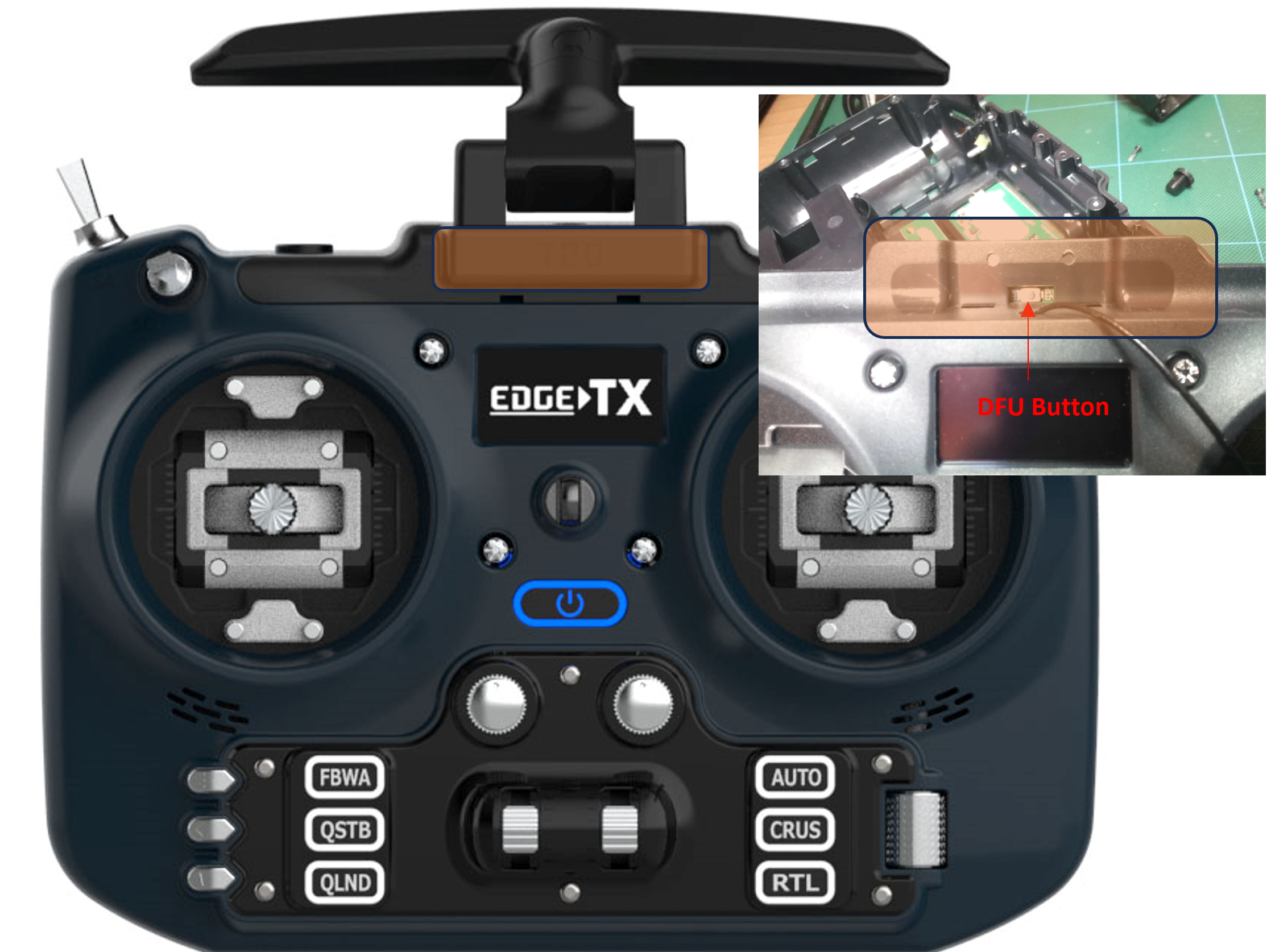
Jumper T-20 - кнопка DFU
Примечание: Для доступа к кнопке DFU на первой версии v1, необходимо отсоединить антенну. Для второй версии v2, используйте зубочистку, чтобы аккуратно нажать на кнопку и не сломать её.
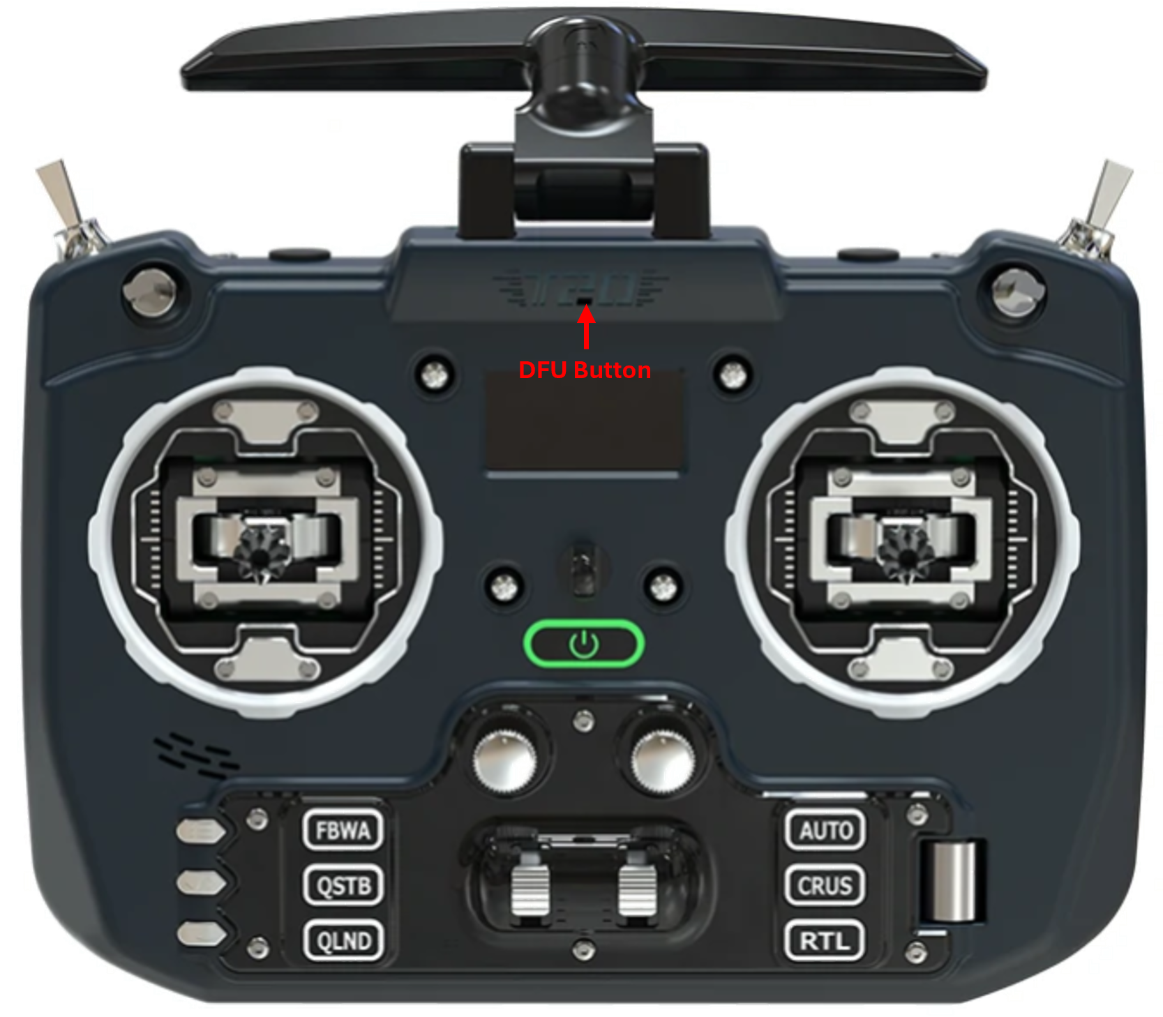
Загрузчик: Выключите аппаратуру управления. Сведите к центру оба триммера (мини-джойстики) и нажмите кнопку включения аппаратуры.
DFU: Выключите аппаратуру управления. Нажмите и удерживайте кнопку DFU, подключите USB-кабель от компьютера, отпустите кнопку DFU.
Jumper T-Lite
Загрузчик: Выключите аппаратуру управления. Зажмите две нижние внутренние кнопки горизонтальных триммеров и нажмите кнопку включения аппаратуры.
DFU: Выключите аппаратуру управления. Подключите USB-кабель от компьютера.
Jumper T-Pro / T-Pro V2
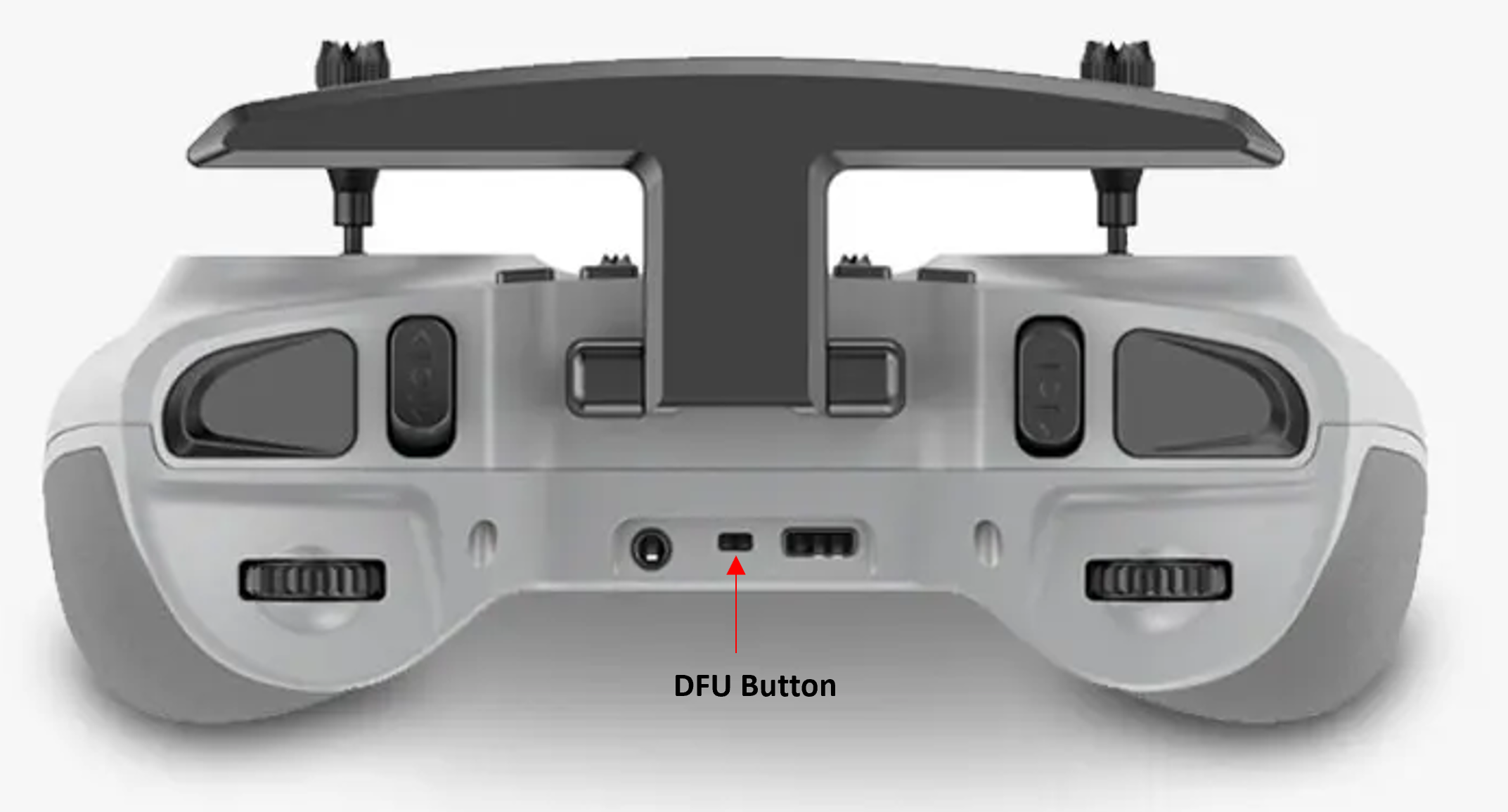
Jumper T-Pro - кнопка DFU
Загрузчик: Выключите аппаратуру управления. Сведите к центру оба триммера (мини-джойстики) и нажмите кнопку включения аппаратуры.
DFU: Выключите аппаратуру управления. Нажмите и удерживайте кнопку DFU, подключите USB-кабель от компьютера, отпустите кнопку DFU.
RadioMaster MT12
Загрузчик: Выключите аппаратуру управления. Сведите к центру триммеры T1 and T2 (сверху от рулевого колеса) и нажмите кнопку включения аппаратуры.
DFU: Выключите аппаратуру управления. Подключите USB-кабель к боковому USB порту (под резиновой заглушкой).
RadioMaster Pocket
Загрузчик: Выключите аппаратуру управления. Сведите к центру оба триммера (мини-джойстики) и нажмите кнопку включения аппаратуры.
DFU: Выключите аппаратуру управления. Подключите USB-кабель к верхнему USB порту аппаратуры.
RadioMaster GX12
Загрузчик: Выключите аппаратуру управления. Сведите к центру оба горизонтальных триммера и нажмите кнопку включения аппаратуры.
DFU: Выключите аппаратуру управления. Подключите USB-кабель к верхнему USB порту аппаратуры (подсветка кнопки питания должна загореться). Зажмите кнопку SG (на левой верхней панели) и кратковременно нажмите и отпустите кнопку питания (нужно короткое нажатие). Теперь вы можете отпустить кнопку SG.
RadioMaster (Остальные модели - Boxer, T12, Zorro, TX16S)
Загрузчик: Выключите аппаратуру управления. Сведите к центру оба горизонтальных триммера и нажмите кнопку включения аппаратуры.
DFU: Выключите аппаратуру управления. Подключите USB-кабель к верхнему USB порту аппаратуры.
Eachine TX16s
Загрузчик: Выключите аппаратуру управления. Сведите к центру оба горизонтальных триммера и нажмите кнопку включения аппаратуры.
DFU: Выключите аппаратуру управления. Подключите USB-кабель к верхнему USB порту аппаратуры.
Bootloader (загрузчик) - это небольшая программа, хранящаяся в постоянной памяти устройства, которая запускается при включении устройства и отвечает за загрузку основной прошивки. Она инициализирует аппаратные компоненты (экран, нажатия кнопок), проверяет целостность основной прошивки и передаёт ей управление, а также может использоваться для обновления или восстановления системы без специального оборудования, например, через USB порт или карту памяти.
Bootloader mode (режим загрузчика) — это специальный режим работы устройства, в котором запускается только программа-загрузчик, не передавая управление основной прошивке. В этом режиме можно обновлять, переустанавливать или восстанавливать прошивку, обычно через USB порт или карту памяти, прежде чем устройство загрузится в нормальном режиме.
DFU (Device Firmware Update) - "Обновление прошивки устройства", специальный низкоуровневый режим работы аппаратуры, в котором все высокоуровневые функции отключены и контроль полностью передаётся внешнему устройству (компьютеру). Позволяет полностью перезаписать встроенное программное обеспечение.
Дополнить документацию
Как принять участие
- Перейдите в наш гит репозиторий, расположенный здесь: https://gitverse.ru/edgetx/edgetx-user-manual-ru
- Для небольших изменений в руководстве пользователя и правок/дополнений к инструкциям, добавьте Задачу в разделе Задачи (вам потребуется авторизоваться в Gitverse), в которой опишите в деталях что и как вы предлагаете изменить.
- Для тог чтобы добавить новую инструкцию, пожалуйста подготовьте вашу статью в формате Microsoft Word (.doc) или используйте Google Docs. Для иллюстрации работы EdgeTX используйте скриншоты из EdgeTX симулятора, желательно разрешением 480 x 272 пикселя. Создайте задачу и приложите к ней вашу статью. Статья будет опубликована после рассмотрения и утверждения. Если вы планируете поработать над открытой задачей (создание статьи, перевод), оставьте комментарий об этом в комментариях задачи, чтобы другие участники не занимались ей. Когда работа будет завершена, приложите результат к задаче для рассмотрения.
- Если вы хотели бы оставить пожелание или предложение о дополнительных статьях и материалах - заведите Задачу на Gitverse.
Настройка режима тренера с помощью мультипротокольного модуля
Prerequisites
In order to setup a wireless trainer connection with the Multi-protocolm Module, you will need the following:
- A student radio with a FrSky D16 capable TX module
- An instructor radio with:
- A Multi-protocol module to serve as the RX
- An additional TX module to use to communicate with the model (protocol does not matter, but must match the protocol use by the RX on the model)
Setup
Ensure that the model is bound to the desired TX module and operational on the instructor radio.
On the Instructor radio, configure the Trainer section of Radio Settings. See Trainer section for more information on how to set this page up.

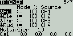
On the Instructor radio, configure the Trainer section of Model Settings. For the Mode, select Master/Multi
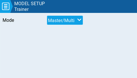
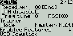
On the Instructor radio, configure the special function Trainer. Designate a switch to activate the mode and make sure the function is enabled.
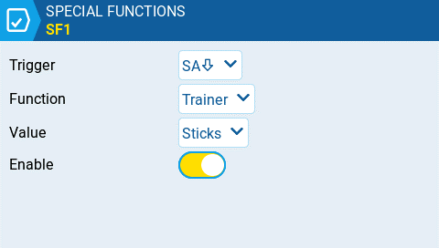
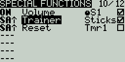
On the Instructor radio, configure the Internal RF and External RF sections in Model Setup. The RF Module's mode that will communicate with the Student radio should be set to Multi, FRSkyRX and RF Protocol: Multi. Also, configure a receiver number. Both the Instructor and Student radios need to use this same receiver number. The other RX module should be configured to communicate with the model.
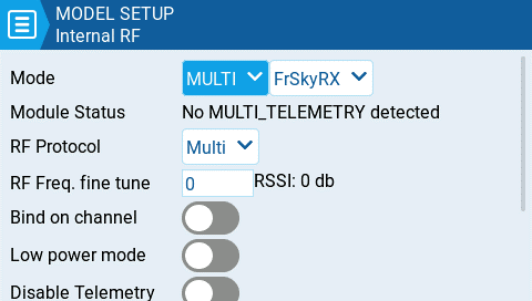
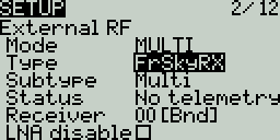
One the Student radio, configure either the Internal RF or External RF (which ever module will be used) to communicate to the Instructor radio. If using a multi-protocol module it should be set to Multi, FRSkyX and RF Protocol: D16. Configure the receiver number to the same number configured in the step above.
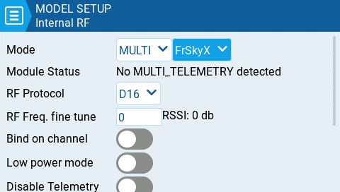
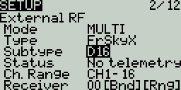
On the Student radio, no configuration of the Trainer section in the Model Settings or Radio Settings is necessary, leave the Mode option in the Trainer section of Model Settings configured to Off.
.png)
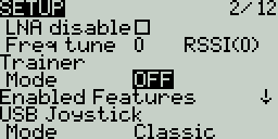
Trainer mode is now configured.
You can test this by watching the channel monitor on the Instructor radio, activating trainer mode via the configured switch and moving the sticks on the student radio. If configured correctly, you should see the stick movements from the student radio on the channel monitor on the Instructor radio.
Use Bluetooth with EdgeTX
The support for Bluetooth in EdgeTX is limited to:
- Bluetooth Trainer Mode
- Bluetooth Telemetry Streaming
The following Bluetooth options are not supported.
- Bluetooth Audio
- Wireless file access and transfers
- Bluetooth joystick
Firmware
To use Bluetooth, you will need a custom compiled version of EdgeTX that needs to be built with the BLUETOOTH=YES CMake flag. You can create customized versions of EdgeTX using the CloudBuild tab on the EdgeTX Buddy website.
Once the correct version of EdgeTX firmware is installed in your radio, the Bluetooth configuration options will be available on the Hardware page of Radio Settings.
Hardware
The only off-the-shelf bluetooth modules supported by EdgeTX are:
FrSky ACCESS PARA Wireless Module
You can also create your own Bluetooth module by purchasing an ESP32 development kit and flashing it with the firmware from following project: https://btwifimod.gitbook.io/untitled/getting-started/hardware
Telemetry Applications
The INAV Telemetry Viewer app can be used on your Android smartphone to view your telemetry data over bluetooth.
Other Important Notes:
- Bluetooth is only supported on radios that have at least one AUX serial port.
- The compile time option Bluetooth will reserve one AUX port (on radios with 2 AUX ports, AUX2 is reserved for Bluetooth) and it will NOT be available in the normal user interface for other purposes.
- EdgeTX Bluetooth trainer or telemetry has nothing to do with internal or external RF module Bluetooth functionality.
- EdgeTX Bluetooth can NOT be used for Bluetooth joystick functionality at the moment.
Configure Advanced Joystick with EdgeTX
General
- Please try the classic mode first. Handling joystick input has undergone many different designs. For example Windows has 6 joystick APIs - all with different quirks.
- Interface mode Gamepad is usually the right one.
- To ease switching between Advanced and Classic mode try using channels 1 - 8 for axis and channels 9 - 32 for buttons.
- After changing the joystick configuration you likely have to disconnect and then reconnect the USB cable. Otherwise systems might still use the old joystick description to read the new data.
Analog Axis
- Most modern applications use the USB HID ID to identify the meaning of an axis.
- Legacy applications frequently use the order the axis where configured in.
- A few applications use the reverse order the axis where configured in.
- Duplicate axis are rarely supported. Some APIs do support two Slider axis.
- Inverted axis: Many applications expect the left and right Y axis to go the other way. The direction can be reversed with Weight -100% or in the advanced Joystick configuration.
- Windows does support "axis" and "sim". However mixing both types is not always supported.
- Linux maps following inputs onto the same axis and uses the input value with the lowest channel number.
- sim Thr + axis Slider → ABS_THROTTLE
- sim Rud + axis Dial → ABS_RUDDER
- axis Wheel + sim Steer → ABS_WHEEL
- Android treats sim Acc and sim Brk as half axis. EdgeTX channel outputs [-100%, 0% and +100%] are interpreted by Android as [0%, 50% and 100%]. Consider following configuration if your physical input is one analog stick:
- sim Acc = input (axis 1: Offset -50%, Func "x>0") mixed with (Weight 200%)
- sim Brk = input (axis 1: Offset -50%, Func "x<0") mixed with (Weight -200%)
Common Axis Mapping
| channel | Android | Betaflight | Dualsense | EdgeTX Classic | EdgeTX pre 2.9 |
|---|---|---|---|---|---|
| CH1 | axis X | axis X | axis X | axis X | axis X |
| CH2 | axis Y | axis Y | axis Y | axis Y | axis Y |
| CH3 | axis Z | axis Z | axis Z | axis Z | axis Z |
| CH4 | axis rotZ | axis rotX | axis rotZ | axis rotX | axis rotX |
| CH5 | sim Brk | axis rotZ | axis rotX | axis rotY | axis rotY |
| CH6 | sim Acc | axis rotY | axis rotY | axis rotZ | axis rotZ |
| CH7 | axis Slider | axis Slider | axis Slider | ||
| CH8 | sim Dpad | axis Dial | sim Dpad | axis Dial | axis Slider |
Similar layouts:
| other controller | use layout |
|---|---|
| OpenTX | EdgeTX pre 2.9 |
| Orqa FPV.Ctrl | EdgeTX pre 2.9 |
| Stadia | Android |
| XBox | Android |
sim Dpad
Sim Dpad emulates a directional pad also known as hat switch or point of view switch. Most application decode the 8 ordinal directions and "center". Some applications only decode the 4 cardinal directions and "center" (e.g. Northeast is treated as North).
| direction | from | to |
|---|---|---|
| North | -100.0% | -88.1% |
| Northeast | -88.0% | -76.4% |
| East | -76.3% | -64.6% |
| Southeast | -64.6% | -52.9% |
| South | -52.8% | -41.2% |
| Southwest | -41.1% | -29.5% |
| West | -29.4% | -17.8% |
| Northwest | -17.7% | -6.1% |
| Center | -6.0% | 5.7% |
| North | 5.8% | 17.4% |
| Northeast | 17.5% | 29.1% |
| East | 29.2% | 40.8% |
| Southeast | 40.9% | 52.5% |
| South | 52.6% | 64.3% |
| Southwest | 64.4% | 76.0% |
| West | 76.1% | 87.7% |
| Northwest | 87.8% | 100.0% |
Axis IDs
| EdgeTX | HID name | USB HID ID |
|---|---|---|
| axis X | X | 0x00010030 |
| axis Y | Y | 0x00010031 |
| axis Z | Z | 0x00010032 |
| axis rotX | Rx | 0x00010033 |
| axis rotY | Ry | 0x00010034 |
| axis rotZ | Rz | 0x00010035 |
| axis Slider | Slider | 0x00010036 |
| axis Dial | Dial | 0x00010037 |
| axis Wheel | Wheel | 0x00010038 |
| sim Ail | Aileron | 0x000200B0 |
| sim Ele | Elevator | 0x000200B8 |
| sim Rud | Rudder | 0x000200BA |
| sim Thr | Throttle | 0x000200BB |
| sim Acc | Accelerator | 0x000200C4 |
| sim Brk | Brake | 0x000200C5 |
| sim Steer | Steering | 0x000200C8 |
| sim Dpad | Hat switch | 0x00010039 |
Buttons
- Buttons are identified by their USB HID ID.
- The meaning of a specific button ID is not standardized.
- Duplicate buttons (e.g. button 1, button 1) are not supported. The button with the higher channel number is used.
- Buttons as axis: Some applications need analog button information. Use a mixer to forward the digital button state to an analog axis.
- Ghost buttons: For Joysticks and Gamepads the required minimum amount of buttons is automatically created. Similarly if only button 15 is configured the missing buttons 0 - 14 are automatically created. These buttons have no input and are always off.
- Android generally supports buttons 0 to 14 with the same mapping as Linux. Support for buttons in bold is mandatory for all Android devices.
- Widows generally supports buttons 0 to 9 with the same mapping as Xbox.
| EdgeTX | Android / Linux | Dualsense | Windows / XBox | USB HID ID |
|---|---|---|---|---|
| button 0 | BTN_A - 304 | square | A | 0x00090001 |
| button 1 | BTN_B - 305 | cross | B | 0x00090002 |
| button 2 | BTN_C - 305 | circle | X | 0x00090003 |
| button 3 | BTN_X - 307 | triangle | Y | 0x00090004 |
| button 4 | BTN_Y - 308 | L1 | left bumper | 0x00090005 |
| button 5 | BTN_Z - 309 | R1 | right bumper | 0x00090006 |
| button 6 | BTN_TL - 310 | L2 | back | 0x00090007 |
| button 7 | BTN_TR - 311 | R2 | start | 0x00090008 |
| button 8 | BTN_TL2 - 312 | create | left stick | 0x00090009 |
| button 9 | BTN_TR2 - 313 | options | right stick | 0x0009000A |
| button 10 | BTN_SELECT - 314 | L3 | left trigger | 0x0009000B |
| button 11 | BTN_START - 315 | R3 | right trigger | 0x0009000C |
| button 12 | BTN_MODE - 316 | home | guide | 0x0009000D |
| button 13 | BTN_THUMBL - 317 | touchpad | 0x0009000E | |
| button 14 | BTN_THUMBR - 318 | mute | 0x0009000F | |
| button 15 | 0x00090010 | |||
| button 16 | BTN_TRIGGER_HAPPY1 - 704 | 0x00090011 | ||
| button 17 | BTN_TRIGGER_HAPPY2 - 705 | 0x00090012 | ||
| button 18 | BTN_TRIGGER_HAPPY3 - 706 | 0x00090013 | ||
| button 19 | BTN_TRIGGER_HAPPY4 - 708 | 0x00090014 | ||
| button 20 | BTN_TRIGGER_HAPPY5 - 709 | 0x00090015 | ||
| button 21 | BTN_TRIGGER_HAPPY6 - 710 | 0x00090016 | ||
| button 22 | BTN_TRIGGER_HAPPY7 - 711 | 0x00090017 | ||
| button 23 | BTN_TRIGGER_HAPPY8 - 712 | 0x00090018 | ||
| button 24 | BTN_TRIGGER_HAPPY9 - 713 | 0x00090019 | ||
| button 25 | BTN_TRIGGER_HAPPY10 - 714 | 0x0009001A | ||
| button 26 | BTN_TRIGGER_HAPPY11 - 715 | 0x0009001B | ||
| button 27 | BTN_TRIGGER_HAPPY12 - 716 | 0x0009001C | ||
| button 28 | BTN_TRIGGER_HAPPY13 - 717 | 0x0009001D | ||
| button 29 | BTN_TRIGGER_HAPPY14 - 718 | 0x0009001E | ||
| button 30 | BTN_TRIGGER_HAPPY15 - 719 | 0x0009001F | ||
| button 31 | BTN_TRIGGER_HAPPY16 - 720 | 0x00090020 |
Joystick Mapping Information for Game Developers
General
- EdgeTX can output joystick / gamepad information via USB HID with ID (VID_1209&PID_4F54 / 1209:4F54).
- EdgeTX performs configurable input processing including dead bands, mixing, and non-linear scaling.
- A wide variety of controllers run EdgeTX. By default all devices output the same "Classic Joystick" report format with 8 analog axis and 24 digital buttons.
- Buttons are digital (0 = off, 1 = on).
- Analog axis have 11 bit resoultion.
Linux: evdev
Linux's evdev API uses open (fcntl.h) with /dev/input/event[...] and read (unistd.h) to read input_event (linux/joystick.h).
identity
- EVIOCGID : device_id.vendor is 4617 / 0x1209
- EVIOCGID : device_id.product is 20308 / 0x4F54
input labels
| EdgeTX | event name | event code |
|---|---|---|
| CH1 | ABS_X | EV_ABS 0 |
| CH2 | ABS_Y | EV_ABS 1 |
| CH3 | ABS_Z | EV_ABS 2 |
| CH4 | ABS_RX | EV_ABS 3 |
| CH5 | ABS_RY | EV_ABS 4 |
| CH6 | ABS_RZ | EV_ABS 5 |
| CH7 | ABS_THROTTLE | EV_ABS 6 |
| CH8 | ABS_RUDDER | EV_ABS 7 |
| CH9 | BTN_SOUTH | EV_KEY 304 / 0x130 |
| CH10 | BTN_EAST | EV_KEY 305 / 0x131 |
| CH11 | BTN_C | EV_KEY 306 / 0x132 |
| CH12 | BTN_NORTH | EV_KEY 307 / 0x133 |
| CH13 | BTN_WEST | EV_KEY 308 / 0x134 |
| CH14 | BTN_Z | EV_KEY 309 / 0x135 |
| CH15 | BTN_TL | EV_KEY 310 / 0x136 |
| CH16 | BTN_TR | EV_KEY 311 / 0x137 |
| CH17 | BTN_TL2 | EV_KEY 312 / 0x138 |
| CH18 | BTN_TR2 | EV_KEY 313 / 0x139 |
| CH19 | BTN_SELECT | EV_KEY 314 / 0x13A |
| CH20 | BTN_START | EV_KEY 315 / 0x13B |
| CH21 | BTN_MODE | EV_KEY 316 / 0x13C |
| CH22 | BTN_THUMBL | EV_KEY 317 / 0x13D |
| CH23 | BTN_THUMBR | EV_KEY 318 / 0x13E |
| CH24 | (no name) | EV_KEY 319 / 0x13F |
| CH25 | BTN_TRIGGER_HAPPY1 | EV_KEY 704 / 0x2C0 |
| CH26 | BTN_TRIGGER_HAPPY2 | EV_KEY 705 / 0x2C1 |
| CH27 | BTN_TRIGGER_HAPPY3 | EV_KEY 706 / 0x2C2 |
| CH28 | BTN_TRIGGER_HAPPY4 | EV_KEY 707 / 0x2C3 |
| CH29 | BTN_TRIGGER_HAPPY5 | EV_KEY 708 / 0x2C4 |
| CH30 | BTN_TRIGGER_HAPPY6 | EV_KEY 709 / 0x2C5 |
| CH31 | BTN_TRIGGER_HAPPY7 | EV_KEY 710 / 0x2C6 |
| CH32 | BTN_TRIGGER_HAPPY8 | EV_KEY 711 / 0x2C7 |
Linux: joystick
Linux's joystick API uses open (fcntl.h) with /dev/input/js and read (unistd.h) to read js_event (linux/joystick.h).
identity
JSIOCGNAME is "EdgeTX [...] Joystick" or "OpenTX [...] Joystick". The middle part ("[...]") is device specific.
input labels
| EdgeTX | read js_event |
|---|---|
| CH1 | JS_EVENT_AXIS 0 |
| CH2 | JS_EVENT_AXIS 1 |
| [...] | [...] |
| CH8 | JS_EVENT_AXIS 7 |
| CH9 | JS_EVENT_BUTTON 0 |
| CH10 | JS_EVENT_BUTTON 1 |
| [...] | [...] |
| CH32 | JS_EVENT_BUTTON 23 |
Windows: DirectInput
Windows's DirectInput uses IDirectInputDevice8::GetDeviceState to read DIJOYSTATE (dinput.h). DIJOYSTATE2 (c_dfDIJoystick2) outputs the same information.
identity
DIDEVICEINSTANCE.guidProduct starts with "4F541209-". The trailing part of the GUID is device specific.
input labels
| EdgeTX | DIJOYSTATE |
|---|---|
| CH1 | lX |
| CH2 | lY |
| CH3 | lZ |
| CH4 | lRx |
| CH5 | lRy |
| CH6 | lRz |
| CH7 | rglSlider[1] |
| CH8 | rglSlider[0] |
| CH9 | rgbButtons[0] |
| CH10 | rgbButtons[1] |
| [...] | [...] |
| CH32 | rgbButtons[23] |
Windows: Multimedia
Windows' Multimedia API uses joyGetPosEx to read JOYINFOEX (joystickapi.h). The older joyGetPos / JOYINFO only support CH1-CH3 and CH9-CH32 with the same mapping as the newer JOYINFOEX.
identity
- JOYCAPS.wMid is 4617 / 0x1209
- JOYCAPS.wPid is 20308 / 0x4F54
input labels
| EdgeTX | JOYINFOEX |
|---|---|
| CH1 | dwXpos |
| CH2 | dwYpos |
| CH3 | dwZpos |
| CH4 | dwVpos |
| CH5 | (not available) |
| CH6 | dwRpos |
| CH7 | dwUpos |
| CH8 | (not available) |
| CH9 | dwButtons & 0x000001 |
| CH10 | dwButtons & 0x000002 |
| CH11 | dwButtons & 0x000004 |
| [...] | [...] |
| CH32 | dwButtons & 0x800000 |
Windows: Raw Input
Windows' Raw Input API uses GetRawInputData (WinUser.h), HidP_GetUsageValue and HidP_GetUsages (hidpi.h).
identity
- RID_DEVICE_INFO_HID.dwVendorId is 4617 / 0x1209
- RID_DEVICE_INFO_HID.dwProductId is 20308 / 0x4F54
input labels
| EdgeTX | HidP_Get[...]Value | UsagePage | Usage |
|---|---|---|---|
| CH1 | HidP_GetValueCaps [7] | 0x01 | 0x30 |
| CH2 | HidP_GetValueCaps [6] | 0x01 | 0x31 |
| CH3 | HidP_GetValueCaps [5] | 0x01 | 0x32 |
| CH4 | HidP_GetValueCaps [4] | 0x01 | 0x33 |
| CH5 | HidP_GetValueCaps [3] | 0x01 | 0x34 |
| CH6 | HidP_GetValueCaps [2] | 0x01 | 0x35 |
| CH7 | HidP_GetValueCaps [1] | 0x01 | 0x36 |
| CH8 | HidP_GetValueCaps [0] | 0x01 | 0x37 |
| CH9 | HidP_GetButtonCaps [0] | 0x09 | 0x01 |
| CH10 | HidP_GetButtonCaps [0] | 0x09 | 0x02 |
| [...] | [...] | [...] | [...] |
| CH32 | HidP_GetButtonCaps [0] | 0x09 | 0x18 |
Windows: Windows.Gaming.Input
Windows' RawGameController uses winrt::Windows::Gaming::Input::RawGameController (winrt/Windows.Gaming.Input.h).
identity
- RawGameController::HardwareVendorId is 4617 / 0x1209
- RawGameController::HardwareProductId is 20308 / 0x4F54
input labels
| EdgeTX | GetCurrentReading |
|---|---|
| CH1 | axisArray[0] |
| CH2 | axisArray[1] |
| [...] | [...] |
| CH8 | axisArray[7] |
| CH9 | buttonArray[0] |
| CH10 | buttonArray[1] |
| [...] | [...] |
| CH32 | buttonArray[23] |
Disable Touchscreen
There are various reasons on why you may want to disable the touchscreen. Unintentional touches during a flight could change your model configuration which can be a risk.
Therefore we can create a global function or special function using the No Touch feature to disable and enable the touch feature. While global functions apply to all models, the special function is defined on individual models.
Disable touch screen with a global function
In the following example we use switch SF to disable the touch screen with a global function.
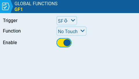
create a global function to disable touch with switch SF
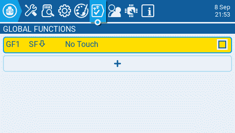
show the global function
Disable touch screen with a special function
Customizable switches or logical switches cannot be used in global functions. But we can use a special function to enable and disable the touch screen with a customizable switch.
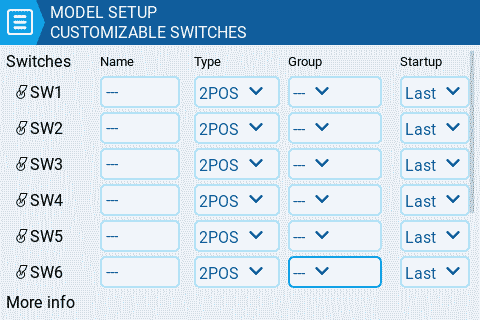
setup of customizable switches
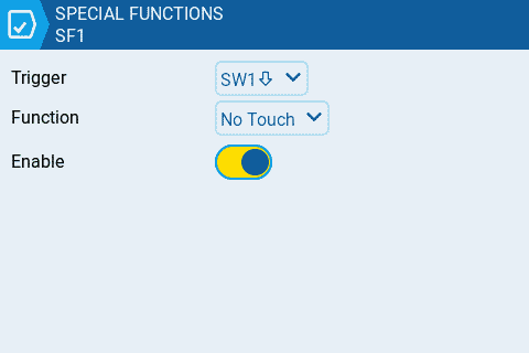
create a special function to disable touch with SW1
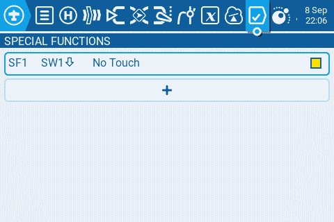
list of special functions
Use Trims to Adjust Global Variables
There are model types where some or all of the trim switches on your radion are not used. Helicopters or drones with a flight controller usually don't need trims Also on many fixed wings you may not need all the 4 trims for throttle, rudder, elevator and aileron.
In the following example our model is a glider. Gliders don't need throttle trim. We also don't need the rudder trim, because we can adjust the rudder with the servo sub trim.
Gliders usually use differential on the aileron mixers. The plane rolls perfect when the differential is set to the correct value.
In this sample we will use the rudder trim buttons to adjust the differential of the ailerons. And we will be able to adjust this using the trims in flight.
Step 1: Disable the trims for rudder and throttle which are not needed. Then we can reuse them for other functionality. Enter the model menu and navigate to the Flight Modes page. Edit FM0 and disable the Throttle and Rudder trims. The yellow highlight color will be gone when the trims are disabled.
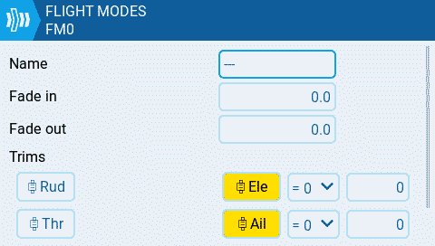
Disable trims for flight mode
You can see the disabled trims also on the flight modes page. They now show a dash
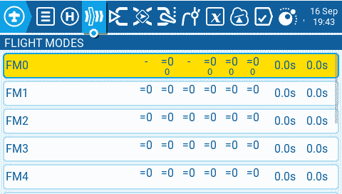
FM0 with disabled trims for throttle and rudder
Step 2: Now we navigate to the Global Variables page and set a default value of 30 for GV1 in FM0
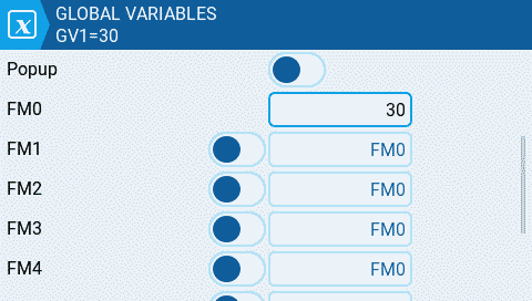
Step 3: We will now create 2 Special Functions to adjust the GV1 value we created in the previous step. Navigate to the Special Functions page and create a new function SF1 for decreasing GV1
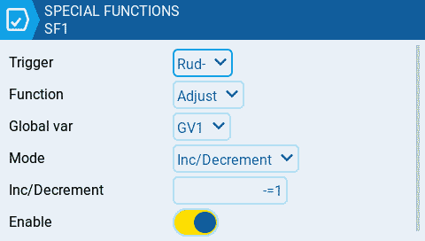
- Trigger is set to the Rud- (rudder trim left)
- Function is Adjust
- Global var is GV1
- Mode is Inc/Decrement
- Inc/Decrement is set to -=1
- Enable the special function
We create SF2 now for increasing the GV1 value
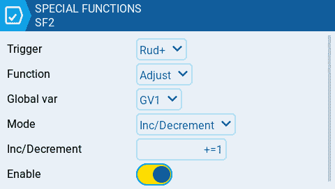
- Trigger is set to Rud+ (rudder trim right)
- Function is Adjust
- Global var is GV1
- Mode is Inc/Decrement
- Inc/Decrement is set to +=1
- Enable the special function
after those 2 special functions are created you can already test the functionality. When you go to Global Variables page you can monitor the GV1 value. The value should change as you use the trims.
Step 4: Now we can adjust our aileron mixer and use the GV1 value for the differential
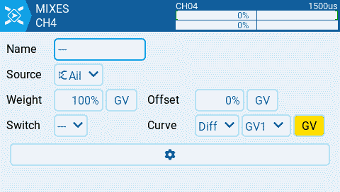
- Curve is set to use Global variables and GV1 is selected
Now you should be able to use the Rudder trim to adjust your aileron differential in flight.
Configure a low battery alert
This How-To shows the configuration of a low voltage battery alert. Let's assume we have a model that is using a 2S Lipo RX battery. We want to configure an alerts when the battery voltage drops below 7.4V.
Ensure that telemetry data is being received by the radio and the sensors have been discovered within EdgeTX before proceeding.
Step 1: Create a logical switch that activates when the battery voltage drops below a defined value.
Press the [MDL] button to open the Model Setup screen and navigate to the Logical Switches tab. Create a new logical switch with the following configuration:
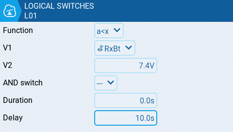
Create Logical Switch LS1 for a low voltage alert
- Function use a<x
- V1 is the telemetry sensor that you want to use for this alert. In this example we are using the RxBt telemetry sensor
- V2 is the voltage where you want the alarm to trigger
- Delay is recommended to configure a delay so that battery sags will not will not cause the alarm to trigger
This logical switch will activate when the TX battery is below 7.4V for the duration of 10 seconds.
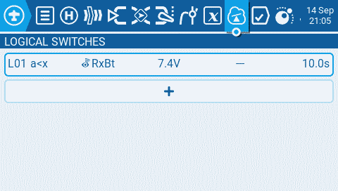
Logical Switch for the low voltage alert
Step 2: Create a Special Function that announces the battery value once the logical switch is activated.
Press the [MDL] button to open the Model Setup screen and navigate to Special Functions Tab and create a new Special function with the following configuration.
- Switch: This is the logical switch that you configured in the previous step. In this example L01
- Func: select the Play Value function from the drop-down so that it will announce the battery voltage when triggered
- Value: Select the telemetry sensor that you configured in the previous step. In this example it is RxBt
- Repeat: Set the value for how often it should repeat the announcement. In this example it is every 10 seconds
- Enable: Enable the Special Function to make it active
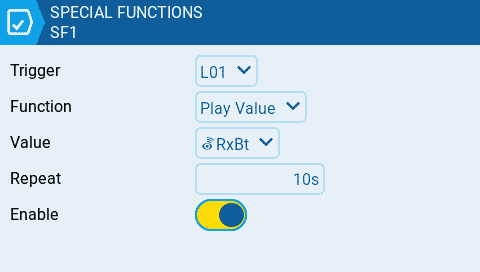
Special Function which plays the low voltage value every 10 seconds
Дополнительные ссылки
OpenTX University - Большое количество информации по радиоуправляемым самолётам.
Большой репозиторий бесплатных картинок разных моделей БПЛА, которые можно использовать в EdgeTX.
- Oscar Liang - https://oscarliang.com/ за множество полезных статей и пример доступной подачи технической информации
- https://rc-soar.com/ - за доступный разбор части концептов, особенно унаследованных из OpenTX
- https://www.apollomaniacs.com/ - за множество полезных и иллюстрированных статей
Благодарности
Отдельное спасибо людям и командам, прямо или косвенно внёсшим свой вклад в создание этого руководства пользователя.
- Участникам сообщества и команде ЦСП Ворон за множество вопросов, ответов и полезной информации
- Руслану Кергет за первую версию русскоязычного руководства пользователя